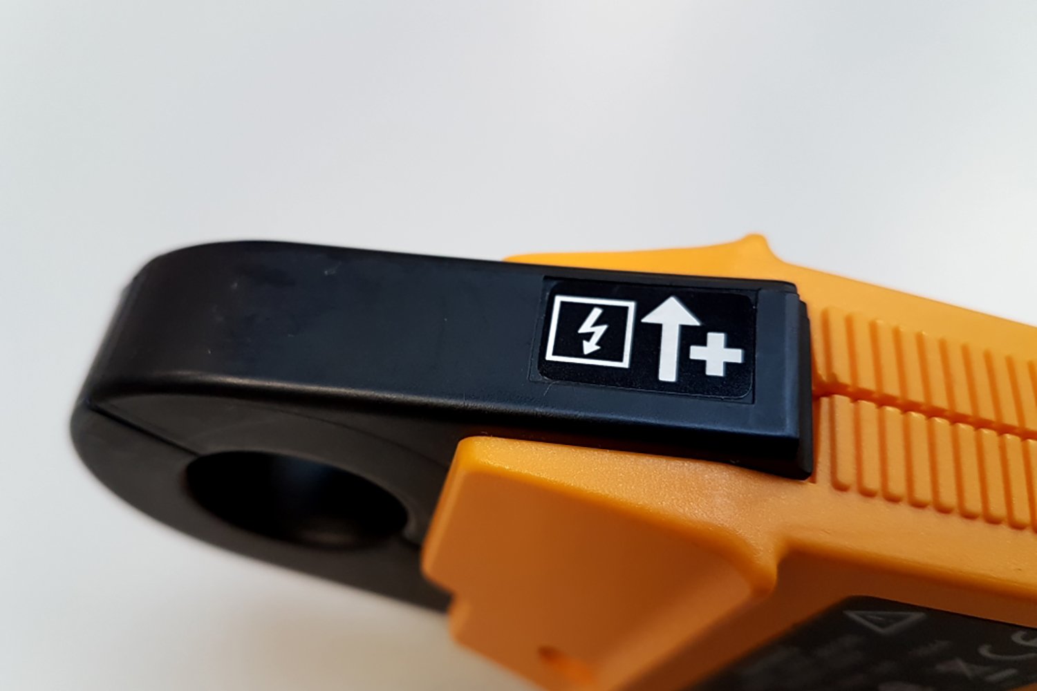


As you can see in the images above, on all current clamps and current clamp accessories there is an arrow placed on there, close to the beak or inside the beak opening.
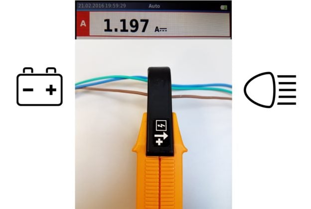
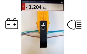
So what should we do with this arrow, and why is it there?
It really depends on the type of instrument you are using, and the application you are working on. In case of a Power or Power Quality measurement it really matters that you pay attention to this arrow!
Influence of current clamp direction on DC circuits
Lets first start with a straightforward application in a DC circuit with a DC sensitive current clamp. Imagine that you use this clamp on a DC circuit in your car for example.
Then when clamping on a wire while the arrow points in the direction of the headlight will generate the same value as when you reverse the clamp on this wire with one exception: the sign will change from positive to negative.
As long as the arrow points to the load, the sign will be positive, and when the arrow points to the power source, the battery in this case, the sign will be negative.
Influence of current clamp direction an AC circuits
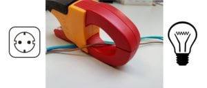
Now we take the clamp to an AC circuit, like a simple lightbulb connected to our 230Vac socket, and do the same. Since we do not have a real “positive” and “negative”, we just get the AC value regardless of how we clamp on the current clamp.
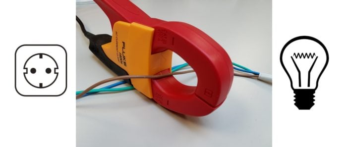 AC example positive
  AC example negative
So here the arrow does not seem to have any influence, or does it?
Watch the waveforms of both situations more closely. What is the difference between the voltage (red) and current (blue)?
 125B out-phase
  125B in-phase
Does the current clamp direction influence your Power measurement?
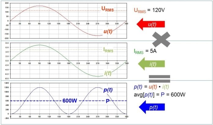 Waveform UIP
The fact that in case of measuring AC current not the sign changes but the phase of the waveform (turns 180 degrees) does not make a difference for the RMS value, for example when using a current clamp on a digital multimeter. However, it does make a difference when you want to measure power!
Since power is calculated by multiplying the waveforms of voltage and current (simplified), the phase between them does change the sign of the power value. The result is that with the arrow pointing to the load you get positive power and with the arrow pointing to the power source you get negative power on your screen.
 Watt negative
In many applications, we expect our loads to consume power and with a reversed clamp it might seem that our load is generating power instead, leading to misinterpretation and faults.
When you have doublechecked your current clamp placement and you still get a negative power… are you measuring on circuits that actually generate power maybe? Like Solar panel inverters, back feeding motor drives or other “loads” that actually can generate power as well.
Bottom line: always make sure that the arrow on your current clamp points to the load, independent of the situation. In this case you always will now how to interpret the resulting value in the instrument you use.