Ground faults can be a frequent and persistent issue for any size solar installation or photovoltaic (PV) array. They can impact system health and reduce productivity. Every solar technician needs to know what they are, how to find them, and how to repair them efficiently.
What is a ground fault?
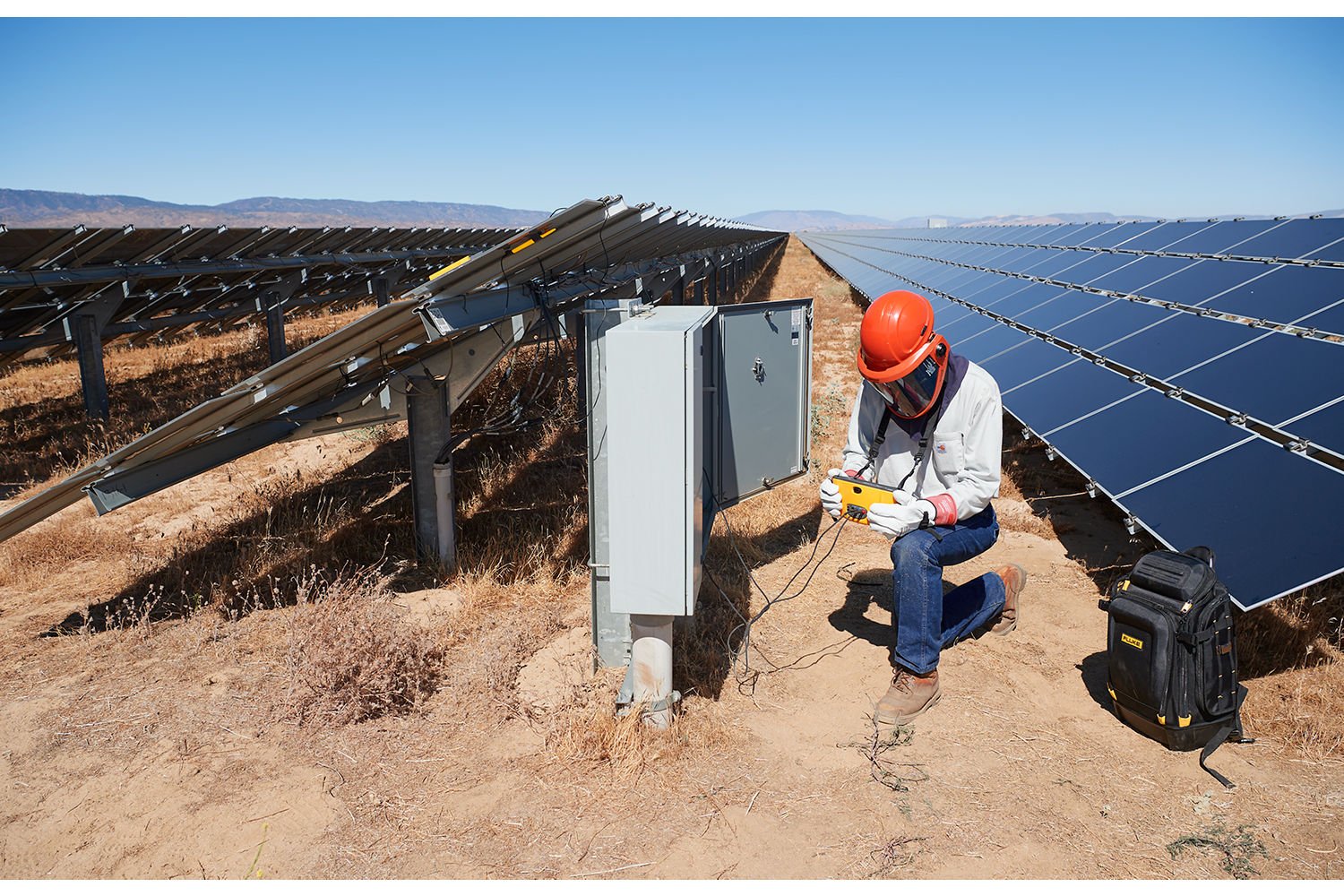
A ground fault is an unintentional connection between a current-carrying conductor and a grounded metal part. On the DC side of a PV array, ground faults typically occur on either the positive or negative wire. They can also happen on one of the ungrounded conductors (L1, L2, or L3) on the AC side of the system. The accidental connection could be with the frame, racking, conduit, electrical box, or any other metal part.
A ground fault can take two basic forms:
- A hard ground fault is a sustained, low-resistance connection between the current-carrying wire and the metal part. This connection remains unbroken over time.
- An intermittent fault is more challenging to locate. It happens when the current-carrying wire occasionally connects to the metal part. A connection can happen during a rainstorm when there’s less resistance, or when a tracker moves into a specific position. Over time, an intermittent ground fault may turn into a hard ground fault.
In PV arrays, several common issues can cause a ground fault:
- Installation errors like pinched wires, wires damaged during installation, or wires secured too close to a racking edge
- Thermal expansion and contraction
- Wind motion that causes wiring to rub against the module frames, conduit, or racking, causing wear on the insulation
How are solar inverters protected from a ground fault?
Solar inverters must have a ground fault detection and interruption (GFDI) device to detect and stop ground faults. It can identify the ground fault, generate an error code, and shut down the inverter.
The amount of current flowing through the ground fault required to trip the inverter's GFDI varies based on the inverter type.
- Isolated transformer-based inverters use a fuse as a GFDI. Some ground faults may not have enough current to blow the fuse and shut down the inverter.
- Non-isolated inverters without transformers use more sensitive GFDIs with a residual current device (RCD). The RCD can identify ground faults at a much lower current level than a fuse.
Working on a PV system always requires PPE
Any time you work on an energized system, it’s essential that you use appropriate personal protective equipment (PPE). In the U.S., the NFPA 70E® safety standards guide PPE requirements based on OSHA safety rules and the hazard levels involved.
Smaller residential PV systems may only require electrically insulated gloves. Larger commercial systems, however, may require flame-resistant clothing, electrically insulated gloves, and an arc flash face shield. Some installations may require a complete arc flash suit to protect against potential hazards. Understand your company's rules and the hazards of the equipment you'll be working on so you can protect yourself with the appropriate PPE.
How to test energized DC PV string circuits with ground faults
A methodical testing procedure helps you locate ground faults efficiently — and most important, safely.Understand expected values before you begin
Before testing to identify the location of a ground fault, you need to know what measurement values to expect — specifically voltage. Module open circuit voltage (Voc) can be found on the module label or data sheet. The PV string voltage is calculated by multiplying the module Voc by the number of modules in series.
De-energize and lockout/tagout (LOTO) where you're working
Isolate the equipment to be tested. Open (turn off) the load break rated disconnect in the section where you’re working — this may be a specific area or every disconnect in the array.
Once the disconnect is off, apply lockout/tagout devices to each component to prevent the system from being re-energized accidentally. Label each LOTO device with the worker's name, phone number, date, and the work being performed. Learn more about lockout/tagout safety for solar power systems here.Inspect the PV array visually
Before conducting any tests, it’s a good practice to visually inspect the array. You can find many ground faults by looking for obvious signs of damage, like burn marks on modules or melted connectors.
Test for current on each string first, then open fuse holders
It's critical that you test for current on both the positive and negative conductors before opening any fuse holders. Double ground faults or installation errors can lead to closed circuits where short circuit current (Isc) may be present. Opening a fuse holder or module interconnection while current is flowing is dangerous. It can create a DC arc that can harm both you and the equipment.
Use a current clamp, like the Fluke 393 FC Solar Clamp Meter, to verify zero current in each PV circuit string before opening the fuse holders. Verify that no current is present, then open the touch-safe fuse holders to isolate each PV circuit string.
Warning: Never measure current in a PV installation with the probe tips of a multimeter. This will cause short circuit current to flow through the multimeter, which may damage the meter. It also creates a safety hazard when you remove the probe tips from the terminals you’re testing.Test PV string voltage
Use a CAT III meter with a voltage rating higher than the PV system voltage (like the Fluke 393). Attach the negative lead from your meter to the negative busbar using an alligator clip. Attach the positive lead from your meter to the positive busbar using another alligator clip.
One string at a time, close the string's fuse holder(s) and record the voltage. Open each fuse holder after testing before moving to the next string. Do this for each string in the combiner box. The results should be close to the open circuit voltage for the PV circuit string. If you identify any outliers, you must determine the source of the voltage mismatch.
With all the positive fuse holders open, remove the negative conductor of the first string from the negative busbar and connect it to the negative lead from the meter. (If the combiner has fuses on the negative side, you can open the fuse holders instead of removing the wire. Close one fuse holder at a time to test that string.)
Connect the positive lead from the meter to the grounding bus bar and record the measurement. A string with no ground fault should have zero volts between the negative and ground.
Meters can often read voltage that drops to zero over time. This is "ghost voltage," not real voltage. Any strings that have true voltage will stabilize at that reading almost immediately, and voltage to ground indicates a ground fault.
Test each remaining string, protecting the free wire ends with a wire nut or electrical tape after testing each string.
Isolate all the negative conductors with a wire nut, electrical tape, or by opening the negative fuse holders. Connect the meter's positive lead to the positive bus bar using an alligator clip. Connect the negative lead from the meter to the grounding bus bar and record the measurement. Close one fuse holder at a time and record the measurement.
A string with no ground fault should have zero volts between the positive and ground. Continue this test with each string, one at a time, to identify any ground faults.
Identify the ground fault location using the location procedure below. Repair any ground faults and restart the inverter.
If the inverter continues to show a ground fault, repeat steps c and d until the fault has cleared. You may also test the conductors from the combiner box to the inverter (or re-combiners) using the procedure for testing de-energized circuits below.
How to test de-energized circuits for ground faults
Ground faults are often present on conductors going from the DC combiner to the inverter. They also occur on the AC side of the system from the inverter to the point of interconnection. These circuits can usually be de-energized by opening disconnects on both ends of the circuit. De-energized conductors have a different test procedure than energized PV string circuits.Isolate, de-energize, and lockout/tagout (LOTO)
Before you begin, open (turn off) each load break rated disconnect in the system section you’ll be working on. Isolate each conductor from electronics and other conductors; you may have to remove the conductor from a terminal.
Once the disconnect is off, apply lockout/tagout devices to each component to prevent the system from being re-energized accidentally. Label each LOTO device with the worker's name, phone number, date, and the work being performed. (Learn more about lockout/tagout here.)
Before un-landing conductors, if required, test for current to prevent damage to the equipment and arc hazards.Use live-dead-live testing to ensure the circuit is de-energized
A live-dead-live test is essential to verify that the circuit is off. First, test your meter on a known voltage source, like an energized circuit or the Fluke PRV240 Proving Unit. Then test the circuit and measure its voltage, which should be zero. Finally, retest the meter on the known voltage source to verify that the meter is still working.
Perform an insulation resistance test to identify the circuit with a ground fault
Never perform an insulation resistance test on a conductor connected to an electronic device. The voltage used during the test may damage electronic circuits.
You can’t test insulation resistance on circuits connected to the ground, like the neutral conductor on the AC side of an inverter. Before you test a grounded, neutral conductor, check that there’s no current in the circuit. Then remove both ends of the conductor from its terminals to isolate it from ground.
Connect the red test lead to one end of the conductor. Isolate the other end of the conductor. You may need to use a wire nut or tape to prevent it from arcing and creating a safety hazard.
Connect the black test lead to ground. Run the insulation resistance test and record the results.
Repeat the test on other conductors in the circuit. Identify any outliers with low resistance that may indicate a ground fault.
How to locate a ground fault in a PV string circuit by the numbers
A PV string circuit without a ground fault will have open circuit voltage (Voc) between positive and negative conductors. It will have zero volts from positive to ground and from negative to ground.
When a ground fault is present, measurement will show Voc between positive and negative conductors. It will also reveal a value other than zero on the positive to ground, negative to ground, or both.
Let's look at an example with voltage to ground on both positive and negative sides:
First, measure between positive and negative. In this string of 16 modules, each with a Voc of 53.82 VDC, we measure 861.12 VDC, the PV string circuit open circuit voltage (16 x 53.83 = 861.12). 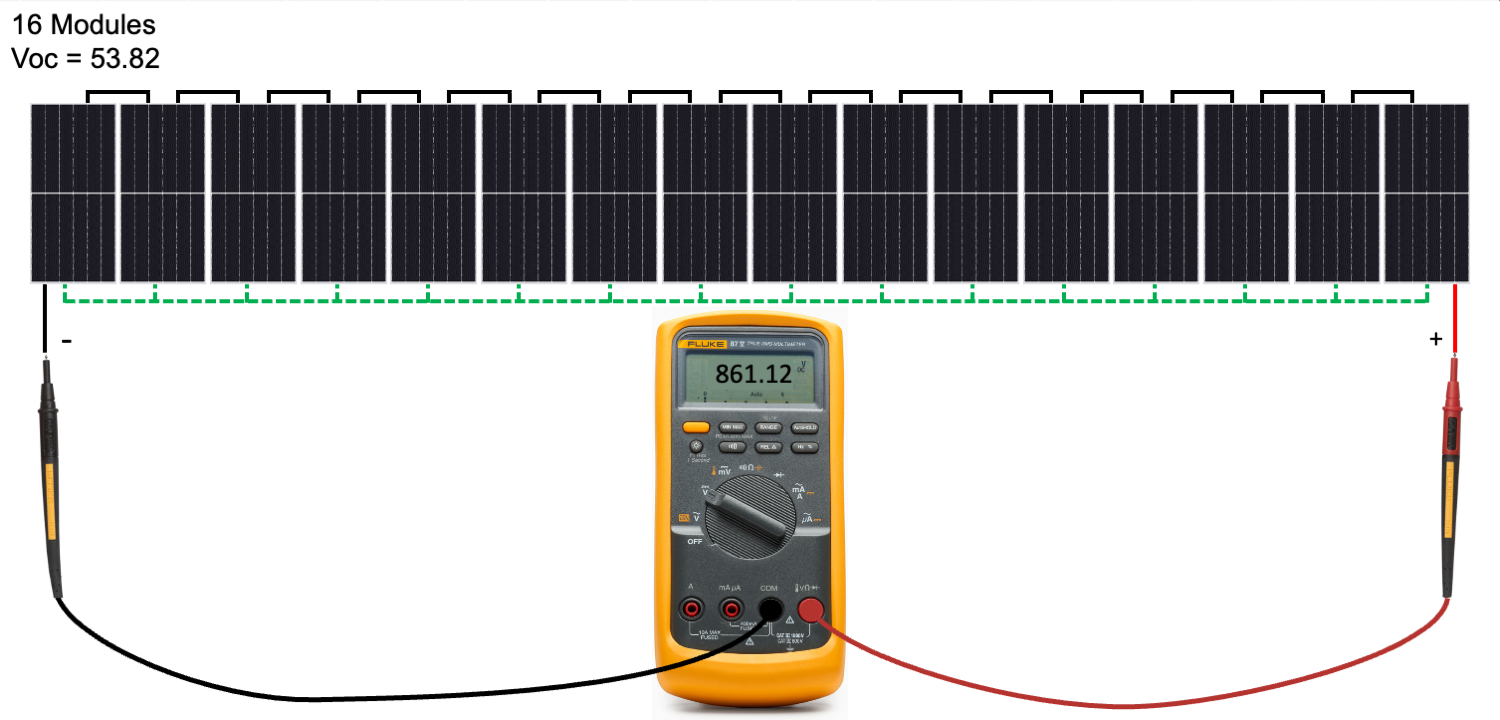
Next, we measure between the positive conductor and ground, and get a reading of 645.84 VDC. 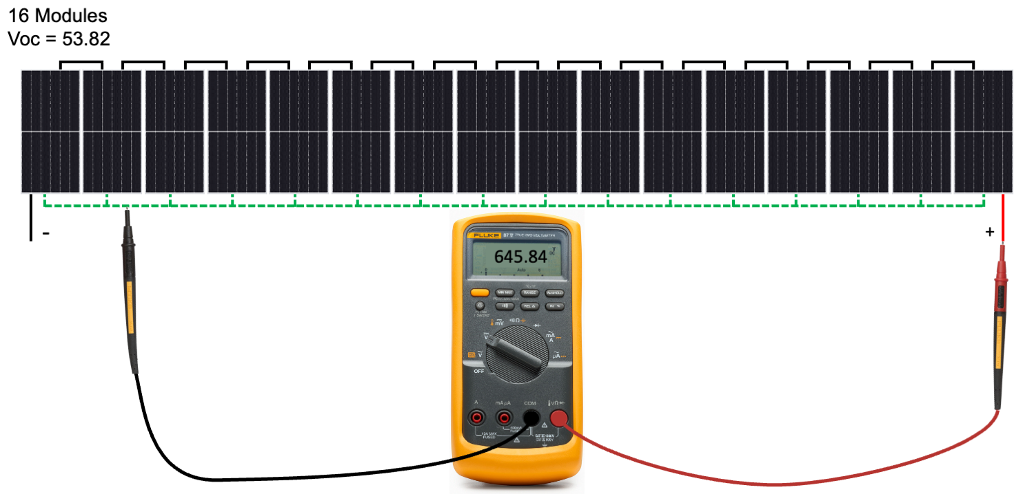
Now we measure between the negative conductor and ground, and get a reading of 215.28 VDC. 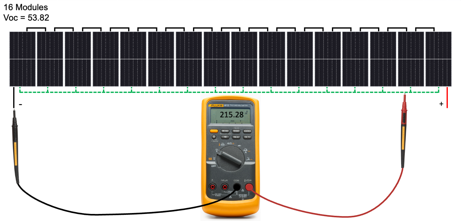
We expected zero volts to ground. However, the measurements indicated voltage to ground on both the positive and negative sides of the PV string circuit. We can divide both readings to ground by the individual module Voc to identify the location of the ground fault.
645.84 ÷ 53.82 = 12
215.28 ÷ 53.82 = 4
These results indicate that there are 4 modules on one side of the ground fault and 12 on the other. So the fault is located between modules 4 and 5. Rarely, module cells can create a ground fault when they contact the module frame. 
Here’s another typical ground fault example with voltage to ground on the negative side.
First, measure between positive and negative. In this string of 16 modules, each has a Voc of 53.82 VDC. Again we measure 861.12 VDC, the PV string circuit open circuit voltage. 
Next, we measure between the positive conductor and ground, and get a reading of 0 VDC, which matches our expectations. 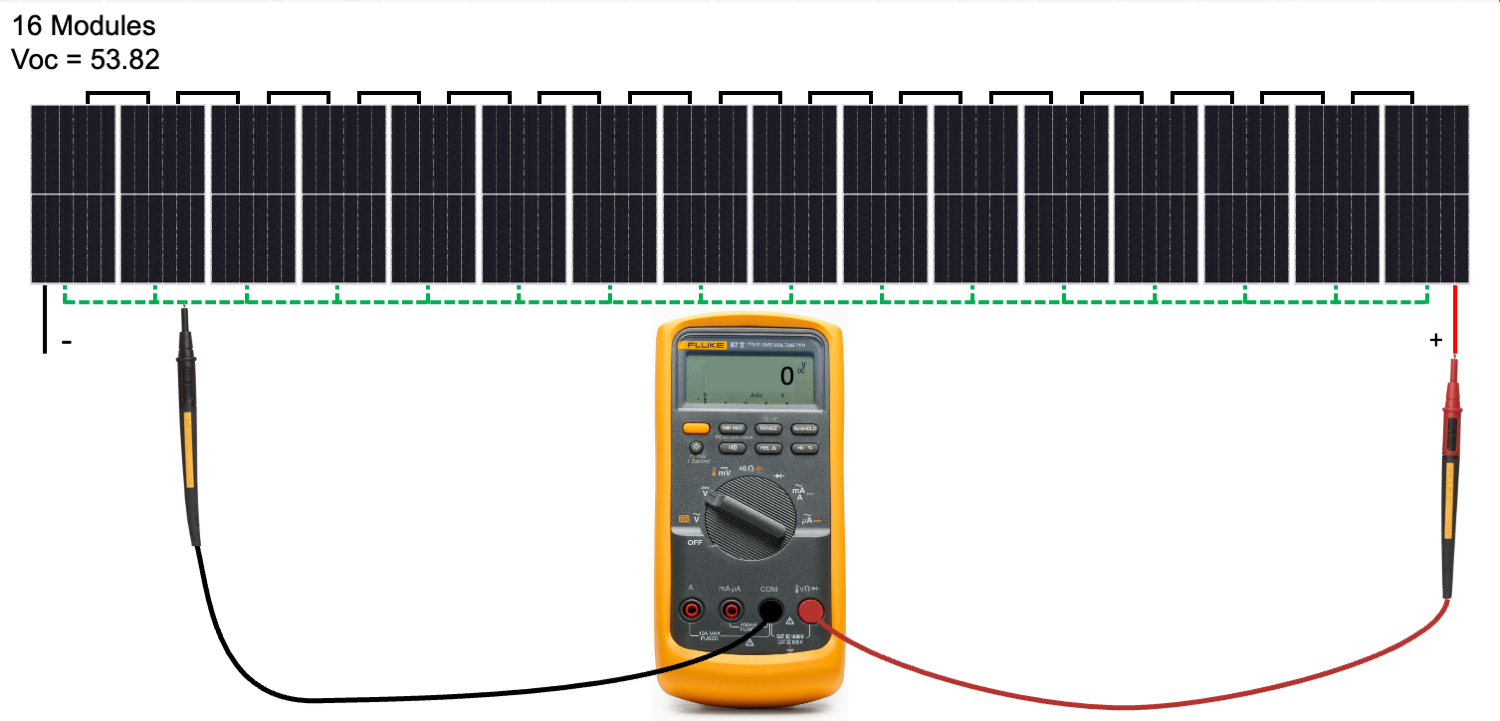
Now we measure between the negative conductor and ground, and get a reading of 861.12 VDC.
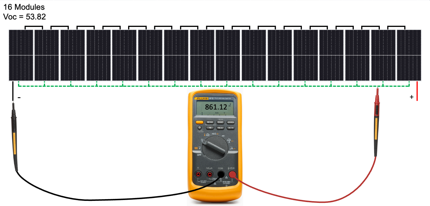
We expected zero volts to ground, but the measurements indicated voltage to ground on the negative sides of the PV string circuit. If we divide both readings to ground by the individual module Voc, we can identify the ground fault location.
0 ÷ 53.82 = 0
861.12 ÷ 53.82 = 16
These measurements indicate that all 16 modules are on one side of the ground fault and zero modules on the other, which means the ground fault is in the positive homerun conductor.
Ground faults in a homerun conductor are relatively common yet easy to miss. One measurement to ground will read zero volts, as expected. But at the same time, the other side will measure the Voc of the entire string. Pay close attention to these measurements so you can find the fault. 
How to use insulation resistance testing to find intermittent ground faults
Insulation resistance testing can be an excellent tool for identifying ground faults, including many intermittent faults. Before testing insulation resistance on any circuit with PV modules, contact the module manufacturer to check that insulation resistance testing through the module is allowed, so you don't void the module warranty.
Never conduct insulation resistance testing on a circuit connected to an electronic device like module-level power electronics or an inverter. Isolate all circuits from power electronics before conducting the insulation resistance test or you may damage those electronic devices.
In larger PV systems, you may not know which section of the array has the ground fault. One way to narrow the search is to use an insulation resistance meter, like the Fluke 1587 FC Insulation Multimeter or the Fluke SMFT-1000 Multifunction PV Tester. The meter can help you identify a subsection of the array with lower-than-normal ground resistance.
For example, in utility-scale systems where multiple combiner boxes are connected to a large central inverter, the data acquisition system may not identify which combiner box has the ground fault. Begin the insulation resistance test process by isolating each combiner box from the rest of the system. Once they're isolated, you can perform an insulation resistance test on each combiner. Comparing results from each test lets you identify outliers that warrant additional testing.
Not all systems will require insulation resistance testing to identify the array segment with a ground fault.
For example, utility-scale systems with string inverters rarely have combiner boxes. Their DC PV circuit strings are run individually directly to the inverter. For these systems, you can skip insulation resistance testing. Use the voltage testing procedure outlined earlier, because you'll know which inverter has the ground fault.
An intermittent ground fault appears only under specific conditions. Insulation resistance testing can often identify PV string circuits with such faults. A meter like the SMFT-1000 or 1587 can help you pinpoint the string with a low resistance to ground.
- Remove the negative wire from the common busbar. If you’re using an insulation resistance tester like the 1587, attach the red lead from the meter to the negative PV string circuit wire. Attach the black lead from the meter to ground.
- Isolate the positive end of the string from other circuits. Run the insulation resistance test and record the results. Use a wire nut or electrical tape on the exposed end of the negative wire, or return the wire to its terminal, before you move on to the next test.
- Continue this procedure with each PV string circuit and identify any outliers which may indicate a ground fault. If you’re using a multifunction tester like the SMFT-1000, follow the procedure prompted by the meter.
Some intermittent ground faults appear only when the system is wet. In that case, you must do your testing under wet conditions. Wait for a rainy day, morning condensation, or spray the array with water before you conduct the tests. Always take appropriate safety precautions, as wet arrays may pose an increased safety risk.
Intermittent ground faults may also result from moving parts, such as tracking solar arrays. The fault may only appear at specific times of the day. In that case, reset the inverter and use the monitoring system to identify the time when the GFDI tripped. Do your troubleshooting around this time to identify the fault location.
How to repair ground faults in PV systems
Once you’ve found the ground fault, you have several options for repairing it.
If the damaged conductor is in conduit or free air, you can replace it with a new, undamaged conductor. A single conductor in a conduit with other conductors may be challenging to replace without removing all conductors from the conduit.
If you find minor damage on a PV string circuit in free air, you can cut out the damaged wire section. Replace it with a field-installed quick connector like an MC4.
- Verify that no current is flowing in the circuit using a clamp meter, like the Fluke 325 True-RMS Clamp Meter, 378 Non-Contact AC/DC Clamp Meter, or 393 Solar Clamp Meter.
- Cut the conductor and remove any damage.
- Place a positive connector on one side and a negative connector on the other.
- Plug in the connectors, ensuring that they’re firmly in place.
- Repeat voltage and/or insulation resistance testing on the circuit to verify the repair.
In some cases, a ground fault will be easy to spot. High resistance generates heat, which may cause a fire and potentially extensive damage. Replace all impacted equipment and conductors.
Ground faults can be a persistent issue for any PV system. They take a toll on system health and productivity. A clear, consistent approach to finding and diagnosing such faults can help you repair them reliably and efficiently whenever they occur.