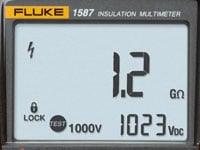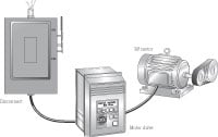
The Fluke 15x7 Series Insulation Multimeter is a new category of test tool that combines a full featured True RMS DMM and a megohmmeter. It's an integrated tool for maintaining and troubleshooting motor systems, electrical distribution, and production equipment.
Carrying this new tool will enable you to test insulation more often, making your maintenance tests more thorough and your troubleshooting more effective. It will also save you time from having to go "back to the shop" to pick up an insulation tester. This application note reviews the measurement functions in this new class of instrument, including two examples that illustrate how these functions work together.
Overview of measurement functions
Higher circuit densities and advances in safety design have allowed engineers to combine multiple instruments without increasing physical size, or compromising on troubleshooting functions or safety features.
The 15x7 Series Insulation Multimeters are both 600 V Cat IV and 1000 V Cat III safety rated. They are designed for use on service entrances up to 600 V and on PWM inverter dc buses up to 1000 V.
The table on the following page lists all of the measurements available in the insulation multimeter, as well as some of the troubleshooting applications.
| Measurement Troubleshooting | Applications |
|---|---|
| Volts AC |
|
| Volts AC, with low-pass |
|
| Volts DC |
|
| Amps with current clamp |
|
| Amps, in-line |
|
| Ohms |
|
| Continuity |
|
| Insulation resistance testing |
|
| Temperature* |
|
| Frequency |
|
| Frequency,with low-pass |
|
| Capacitance | Verify the proper capacitance of:
|
| Diode |
|
| Min/Max/Avg recording |
|
| Other |
|

Example: Machine quits during crunch time
A 230 V across-the-line motor turns the blower in a pneumatic conveyance system. The motor uses an electromechanical starter. Toward the end of the quarter, when the plant is trying to ship as much as possible, the motor sounds awful for a few minutes and then blows a fuse. It seems to be happening more often.
Since de-energized tests are always safer, you decide to perform those first. You use proper lock out / tag out procedures to be sure the circuit stays de-energized while you are testing.
You check the insulation between the phases and ground. You start your testing at the starter since this will allow you to check the conductors feeding the motor as well as the windings. At the starter you attach the "-" lead from the insulation multimeter to the metal conduit using the supplied alligator clip. You set the test level to 500 V and probe one of the phases with the "+" test probe. The reading is 0.8 megohms, which is lower than you would expect. Since the motor windings are connected within the motor and present a low-resistance path for dc, all of the phase conductors and windings are lifted to the test voltage.
So one of the phase conductors or motor windings has poor insulation resistance, but which one? You disconnect the motor at its conduit box. You check the insulation resistance between the motor windings and the motor frame (ground). The windings have insulation resistance in the gigohms. The problem isn't in the motor.
You take a closer look at the motor conduit box and you notice some discoloration. When the motor was installed someone stripped too much insulation from the phase B conductor. When the machinery was used heavily, the conductor would arc to the bonded conduit. The build up of carbon made it easier for the short to occur, but it also made it easy for the insulation multimeter to find the problem.

Example: Bad drive, bad motor, or neither?
A PWM motor drive is used for driving a material conveyor. It is connected to the power system through a fused disconnect and until recently it worked fine. Sometimes the motor runs just fine, but often after running for 15 to 30 minutes, it blows the fuse feeding the drive on B or C phase. It seems random as to whether B or C opens. After the fuse is replaced and the drive is re-energized, the only fault it reports is a loss of power. What's the problem and why has it just shown up now? Has the drive gone bad?
Of course you take along your insulation multimeter. Again, since you don't know why the fuse is opening, you decide to test the de-energized system first. You lockout and tagout the disconnect.
It's unlikely that this is a problem with the motor, since the motor drive has sophisticated diagnostics that constantly monitor the drive outputs. If the problem were with the motor, the drive would probably fault before the fuse blows. The fuse opening certainly indicates some sort of overcurrent condition, like an intermittent short. So you start at the line side of the drive.
You start by checking the conductors from the disconnect to the drive. It's not a good idea to apply insulation test voltages to the input of the drive, so you disconnect the drive from the line. You use your insulation multimeter to check the insulation resistance of each conductor to ground and of each conductor to the other two. The insulation resistance readings are all over 1 gigohm, so it doesn't seem to be an insulation problem.
You want to rule out the input circuitry of the drive. The drive uses a diode rectifier bridge on its input and you use the diode function of the meter to check it. But you don't find any shorted or open diodes.
The de-energized testing ruled out cable shorts and shorts in the drive. So you reconnect the drive, button everything up, and power the system. The drive powers up normally. You make sure you're wearing appropriate personal protective equipment before opening any of the enclosures to take measurements.
The motor starts perfectly and you decide to verify the output of the drive. You use the low-pass voltage function to measure the drive output. This feature of the insulation multimeter uses a low pass filter on the PWM waveform and allows you to measure the voltage of the PWM envelope rather than the individual pulses. This allows direct comparison of the drive readout to the meter display. You find that the phases are balanced and consistent with the drive display. You also use the low-pass function to check the output frequency of the drive. The output frequency makes sense when compared to the drive display. It seems that the drive is performing properly.
Next, you move to the input of the drive. You measure the line voltage on the input and phase A is significantly lower than the other two phases. Then you connect a current clamp to your insulation multimeter and check the phase currents. You find that the currents on phases B and C are too high and the current on phase A is too low. It turns out the drive and motor are both fine. Something has thrown the line voltage out of balance.
By tracing the line, you discover that someone has wired an unusual single-phase industrial oven on A phase without telling anyone. This was causing the voltage unbalance. The drive was drawing more current from the other two phases to make up the difference and it was a race to see which fuse opened first.
The oven was rewired and the motor has run fine ever since. By using the insulation multimeter you were able to quickly diagnose the problem and verify the integrity of the insulation systems in the process.