The “manufacturing” process here relies on “shots” of laser energy focused on a target the size of a BB.
The product: a nuclear reaction six times hotter than the core of the sun . . . and a growing understanding of fusion reactions that could one day free the planet from dependence on dwindling fossil fuels.
Here at the National Ignition Facility (NIF) at California’s Lawrence Livermore National Laboratory, scientists are working to create nuclear fusion reactions that unleash more energy than their lasers put in—the definition of “ignition.” It’s a first step in a process that could one day bring “star power”—clean nuclear fusion energy—down to earth.
Each full-system laser shot brings 192 separate laser beams together from all directions in a billionths-of-a-second blast to heat and compress the tiny target of tritium and deuterium. Those 192 beams—up to 1.8 million joules of ultraviolet energy—must be focused with ultimate precision. If you could stand on the pitcher’s mound in San Francisco and throw a strike at Dodger Stadium in Los Angeles, 350 miles away, you’d be that accurate.
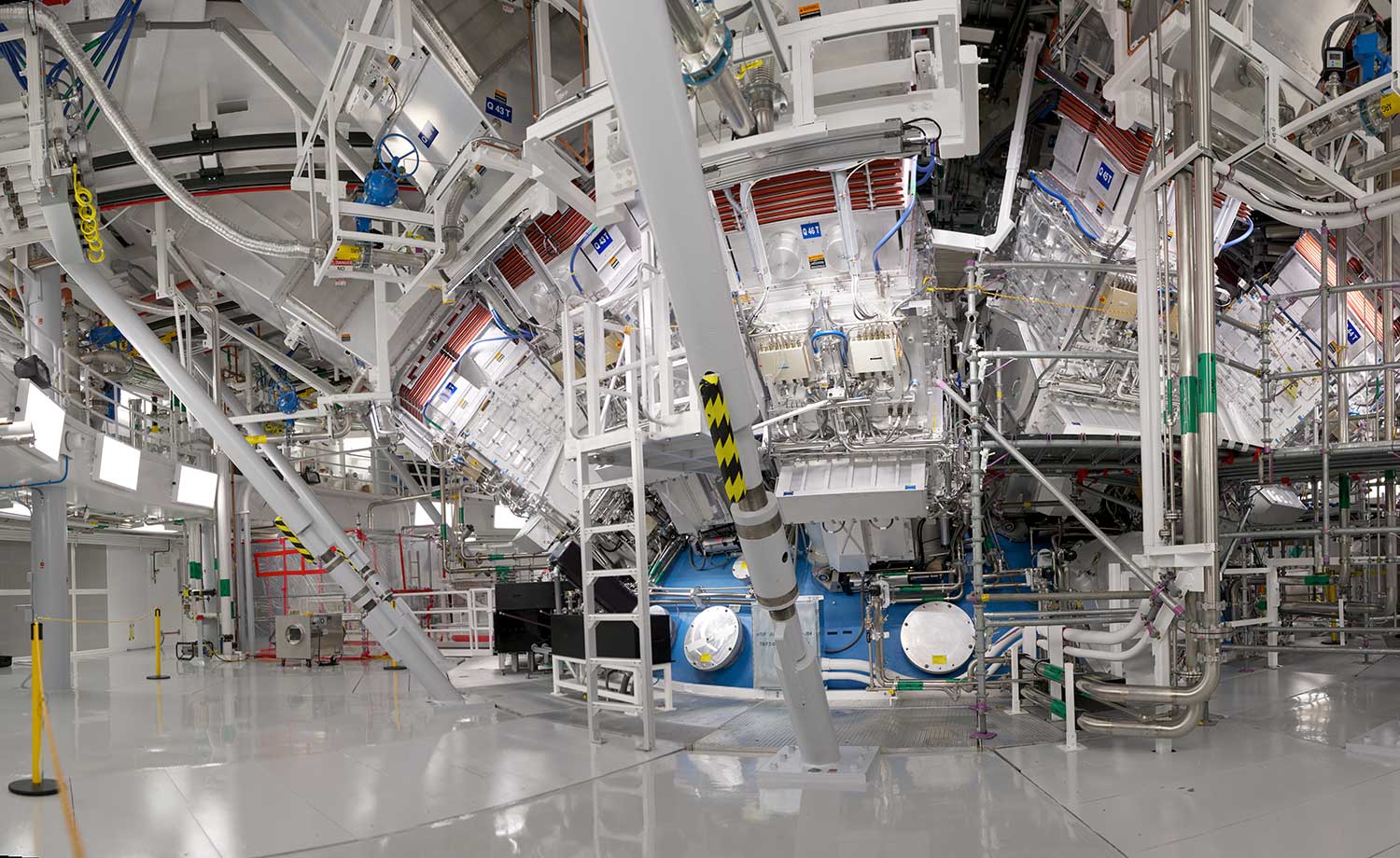
It takes a lot of facility and equipment to fire each test shot. The main NIF building stands ten stories tall and operates 24x7. It houses the world’s highest energy laser and the largest optical instrument ever built, a combination of 7,500 large (meter-size) optics and more than 26,000 smaller optics. The ignition shots release radiation, so managing for radiation safety is critical.
It’s all orchestrated through one of the largest automated control systems ever designed for a scientific machine, a system that includes more than 60,000 control points and 850 computers. Success depends on some 6,000 instruments; valves; pressure, temperature, and humidity sensors and transmitters—each individually tracked in the NIF database. Everyone must be calibrated.
A world of power and precision
“The only equivalent to what we do here is a NASA countdown for a shuttle launch,” said Travis Averill, NIF Calibration Program Manager. “If things aren’t maintained and calibrated then they aren’t reliable and repeatable. That makes calibration essential, from the smallest inch-ounce torque screwdriver that assembles the optics to oscilloscopes that calculate record-setting neutron yields. If we don’t calibrate our two floors of HVAC equipment, you’ll get an out-of-spec excursion in temperature. The way the laser beams go through the gas will change, and you’re not going to hit the exact spot you’re trying to hit.”

How do technicians manage such a huge and complex facility? “We use GUIs (graphical user interfaces) in the main control room, where the majority of our facility monitoring is taking place,” Averill said. “This gives us real-time dynamic readings and control on almost everything.”
Full loop calibrations
The key is to make sure that the thousands of networked components and sensors sending signals to the control room deliver accurate readings through the 24 V DC control network to the GUI screens. So, Averill performs “full loop” calibrations to the readings that appear on the screens, not the outputs at the remote sensors and transmitters. “We calibrate to the GUI screen readout every time, to remove any and all error that we can. I am a huge believer in full loop calibrations,” he said.
To calibrate a temperature sensor, for instance, Averill will connect his Fluke Calibration 9142-P Field Metrology Well, fitted with an internal Fluke Calibration 5608 reference standard, combined with a Fluke 754 Documenting Process Calibrator-HART. He sets the metrology well to generate a specific test temperature—say 60, 70, or 80 degrees F (15.6, 21.1, or 26.7 degrees C)—then inserts the temperature element or sensor. After the temperature stabilizes, he radios the control room to verify the GUI reading. The goal is a control room reading that varies no more than .10 degrees F from the dry-well setting. A reading of 56.10 degrees would meet standards, but 56.11 degrees would be out of tolerance.
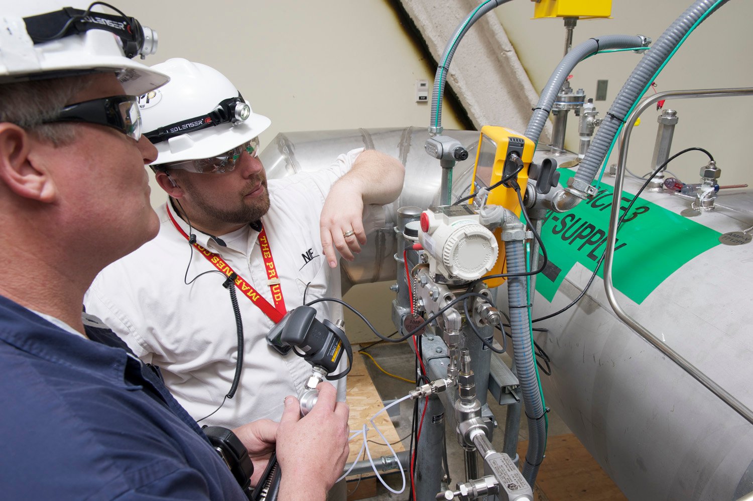
“If the as-found data meets specifications, we won’t adjust it,” Averill said. “If it’s out of tolerance, the first thing we’ll do is a loop check. We plug into the 754 HART communicator, and we talk to the transmitter, and we actually tie into the current. We’ll hook up in series and monitor the 4-20 mA. I’ll tell the transmitter to output what it thinks is 4 mA, and we’ll measure the result. At the same time, I’m expecting the GUI to read 56.00 degrees,” Averill said.
“My mA measure is typically tied into the 754, because it does a multitude of functions. That’s the great part about it. I can use it to talk to my HART communicators, and I can also use it to measure the mA, which should be a reading in this case of 56 degrees. I’ll take that 4 mA output and I’ll loop it through my 754 calibrator, and actually take a measurement on it. So I have a displayed process-variable analog output, which is what it thinks it’s putting out, and I have an actual measured output of mA. By doing that test I’m actually calibrating the transmitter output function and making sure it is within specification. This kills two birds with one stone. It takes less time to do it, with fewer hookups.”

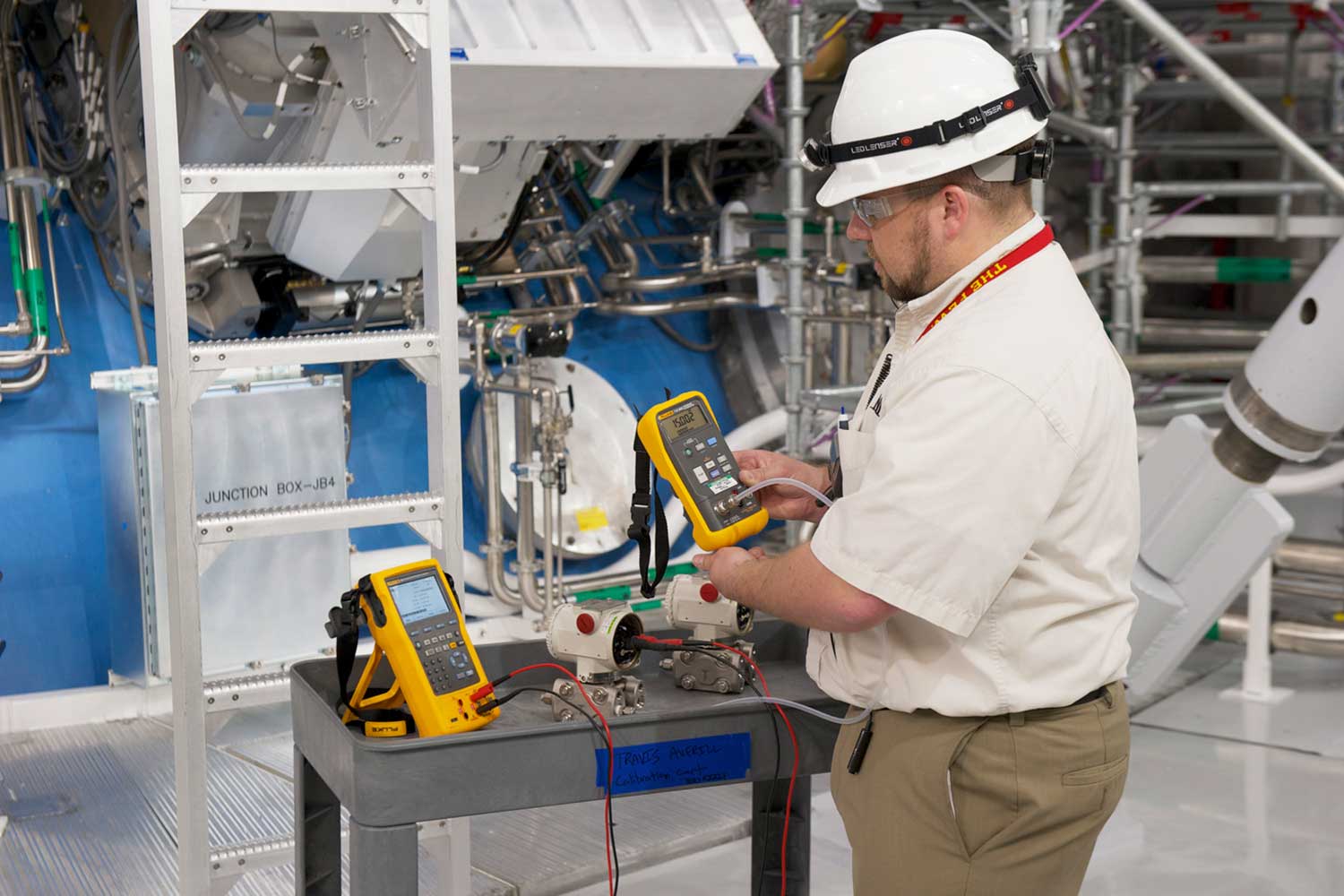
Travis Averill and Mark Jensen at a test point. To maintain precision performance, every test point is on a schedule to be tested and calibrated.
If the transmitter’s output has drifted, Averill will adjust its output (the HART transmitters in use are programmable) so that readings at the GUI match the temperature the sensor sees. The process for pressure calibration is similar. Averill again uses the Fluke 754 or 744 Documenting Process Calibrators, together with the Fluke 719 Portable Electric Pressure Calibrator, plus a portable hand pump that produces its own test pressure.
Something greater
Averill learned his calibration skills during five years as a US Marine, calibrating the avionics on FA-18 Hornet jet fighters. He then worked two years for a third-party calibration provider, working mainly in the biomedical and pharmaceutical fields. “The work I’m doing now fills the need to do something greater than myself that the USMC gave me,” he said. “In 10, 20, or 30 years, when fossil fuels are depleted and the world is needing energy at a capacity much higher than today, fusion energy will be what powers us.”
Staying operational
Before Averill arrived, much NIF calibration was done by local independent labs. Today more work is done in-house, and that helps keep NIF on schedule, firing shots daily and sometimes more frequently. “One of the hardest things is to do the calibration while still staying operational and not affecting the shots,” Averill said. “What pays the bills around here is firing shots and getting toward the goal of fusion.”
Averill has relied on Fluke and Fluke Calibration instruments since his Marine Corps days, and he has some ideas for other calibration professionals.
For calibrating temperature sensors, “buy a field metrology well or two,” he said. “They will obsolete a liquid bath in every way for lab and field applications. What you spend on it you will save in time after the first few uses, guaranteed.” Profound improvements in control and accuracy were made utilizing the Fluke Calibration 9142-P Field Metrology Well.
The Fluke Calibration 9142-P is an industrial temperature loop calibrator designed for performing transmitter loop calibrations, comparison calibrations, or simple checks of thermocouple sensors. Weighing less than 18 lbs. (8.2 kg), it is quick to reach temperature set points, yet is stable, uniform, and accurate. “We can set up temperature points and walk away, and have it logging on our GUI screens. Come back 45 minutes later, make any adjustments if needed, and the only hands-on time we spent was hooking and unhooking the transmitters. I purchased a second one because you can use two at a time very easily. If I was in the field day today I might even want three to juggle, just to streamline the process.”
Training the team
Calibration at NIF involves two teams of maintenance technicians: those who work on conventional facilities and others who focus on beam path utilities systems—40 in all.
“More often than not they work together, so that everyone has a chance to share their knowledge and experience in maintenance and calibration tasks,” Averill said. “Doing so has brought our technical excellence to some of the highest levels I have ever seen.”
In addition to using the right calibration tools, Averill said a key to success is ensuring team members understand why certain tests are needed, and how to do them. He has written more than 50 calibration procedures to help.
“Where the technicians get lost is when they are blindly following procedures that they do not understand,” he said. ”One of the main tricks I can offer is writing the procedures with technical eyes and ears, as if you are standing there next to the technicians telling them verbatim what to do, and what to look for if something isn’t going right.”
If problems are found, the maintenance team can refer to failure mode and effects analysis (FMEA) documents written ahead of time, so they don’t have to figure out all the problems in real time. Spares for many pieces of equipment are on hand, so operations can be quickly restored.
There is no time to waste. The target to achieve nuclear fusion is late in 2012, so Averill and the rest of the NIF staff—many of them former US Navy nuclear engineers—know there’s no time to waste.
“This has been 50 years in the making,” Averill said, “And we’re less than a year away. It’s exciting around here.”
The National Ignition Facility: Shooting for the stars
What is NIF?
The world’s largest, highest-energy laser, with 192 laser beams that deliver on target 60 times as much energy as any previous system, creating the conditions to achieve the world’s first self-sustaining fusion reaction with energy gain in a laboratory setting. The project is funded by the US Department of Energy’s National Nuclear Security Administration.
Why NIF?
To better understand the physics of nuclear weapons, to give scientists the knowledge to create fusion energy, and to explore basic astrophysical, materials, and nuclear science. What is the timeline? NIF began operations in March 2009 and started producing laser shots in 2010. The goal to achieve fusion (ignition) is late in 2012. It may take 10 to 20 years more to establish fusion as a source of energy.

Why fusion energy?
Laser Inertial Fusion Engine (LIFE), a concept being developed at Lawrence Livermore National Laboratory, has the potential to meet future energy needs in a safe, sustainable way. Among the advantages of fusion:
- The nature of the fusion reaction ensures against a runaway chain reaction or “meltdown.”
- A fusion plant would be carbon-free and produce considerably lower amounts of radioactive byproducts than today’s nuclear plants.
- The fuels required to generate fusion energy are relatively abundant on earth.
Another approach to fusion energy is the magnetically controlled plasma fusion reactor. Experiments with this technology will begin in France in 2018.
Tools to keep laser test shots firing…and the search for fusion energy moving ahead
Calibration Program Manager, Travis Averill of the National Ignition Facility (NIF) uses a long list of Fluke and Fluke Calibration instruments to keep laser test shots firing and the search for fusion energy moving ahead.
Among the tools in Averill’s box:
- Fluke Calibration 1523 Reference Thermometer
- Fluke Calibration 5608 Secondary Platinum Resistance Thermometer with Calibration Options
- Fluke Calibration 5610 and 5611 Secondary Reference Thermistor Probes
- Fluke Calibration 7102 Micro-Bath Thermometer Calibrator
- Fluke Calibration 9102S Handheld Dry-Well
- Fluke Calibration 9142 Field Metrology Well with Process Option
- Fluke 772 and 773 Milliamp Process Clamp Meters
- Fluke 789 ProcessMeter™ Loop Calibration Multimeter
- Fluke 741B Documenting Process Calibrator
- Fluke 744 Documenting Process Calibrator with HART capability
- Fluke 754 Documenting Process Calibrator-HART
- Fluke 700P Pressure Modules (P01, P22, PD04, P06, P22, P27, P29)
- Fluke 719 Portable Electric Pressure Calibrator
- Fluke 434/PWR Three Phase Power Quality Analyzer (discontinued, suggested replacement: Fluke 1770 Series Three-Phase Power Quality Analyzer)
- Fluke 1587 Insulation Multimeter
- Fluke 233 Remote Display Multimeter
- Fluke 112, 177, 26III, 77, 79III, 8060A, 87, 87III, 87V Multimeters
- Fluke T+PRO Electrical Tester
- Fluke Ti25 Thermal Imager (discontinued, suggested replacement: Fluke TiS55+ Thermal Camera)