Use the 1586A Super-DAQ to automate temperature sensor calibration The 1586A Super-DAQ Precision Temperature Scanner provides a unique feature for automating sensor calibration that can greatly increase your lab productivity—without a PC and software. When the Super-DAQ is connected to a Fluke Calibration dry-well or fluid bath, it can control the temperature source to run the calibration automatically. You simply program the number of set-point temperatures and their values, select a scan sequence, assign a reference channel, and set the required stability band.
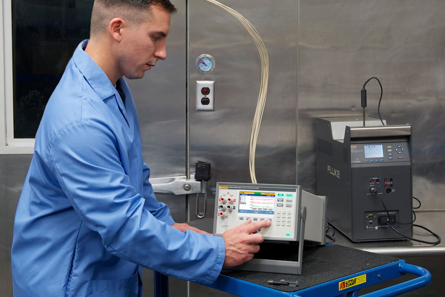
The Super-DAQ monitors the temperature source’s stability through the reference channel, collects the data from the reference probe and the unit under test (UUT) once stabilized, and then advances to the next set-point temperature.
After you configure and start the test, you can walk away to work on other things.
One temperature source can be connected to the Super-DAQ at a time. The Super-DAQ can control many different types of tools for temperature sensor calibration.
- Field Metrology Wells
- Metrology Wells
- Handheld Calibrators
- Field Dry-Well Calibrators
- Thermocouple Furnace
- Dual Block Dry-Well
- Micro Baths
- Compact Baths
- Deep-Well Compact Baths
- Triple Point of Water Maintenance Bath
- High Temperature Oil Baths
- High Temperature Salt Bath
- Cold Temperature Baths
- Deep-Well Baths
How to set up an automated sensor calibration
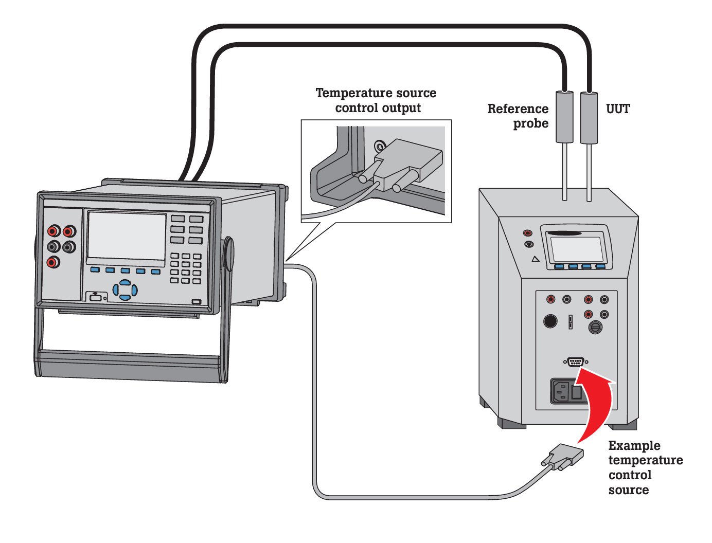
Step 1: Connect the RS-232 cable
Connect a DE-9, null-modem, female-female RS-232 cable from the Super-DAQ rear panel to the RS-232 port of the temperature source. Ensure that the baud rate of the temperature source matches the Super-DAQ. The default is 9600. You can designate any channel as the reference probe including the front panel channel (Ch 001). Note: The Super-DAQ does not record temperature data from the temperature source’s controller or Process Electronics input. All measurement, stability monitoring, and data collection are done through the Super-DAQ.
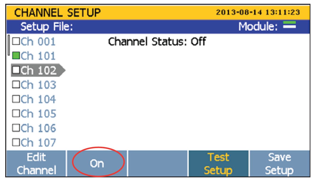
Step 2: Select the channels
Press the Channel Setup hard key, select a channel to be enabled and press ON (F2).
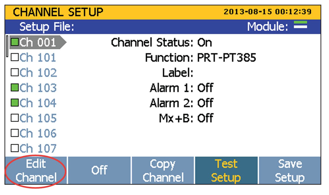
Press the Edit Channel soft key, set Function to Thermocouple, Thermistor, or PRT. Choose the appropriate parameters for the function selected. Configure additional channels. Press Back when finished.
Step 3: Select test parameters
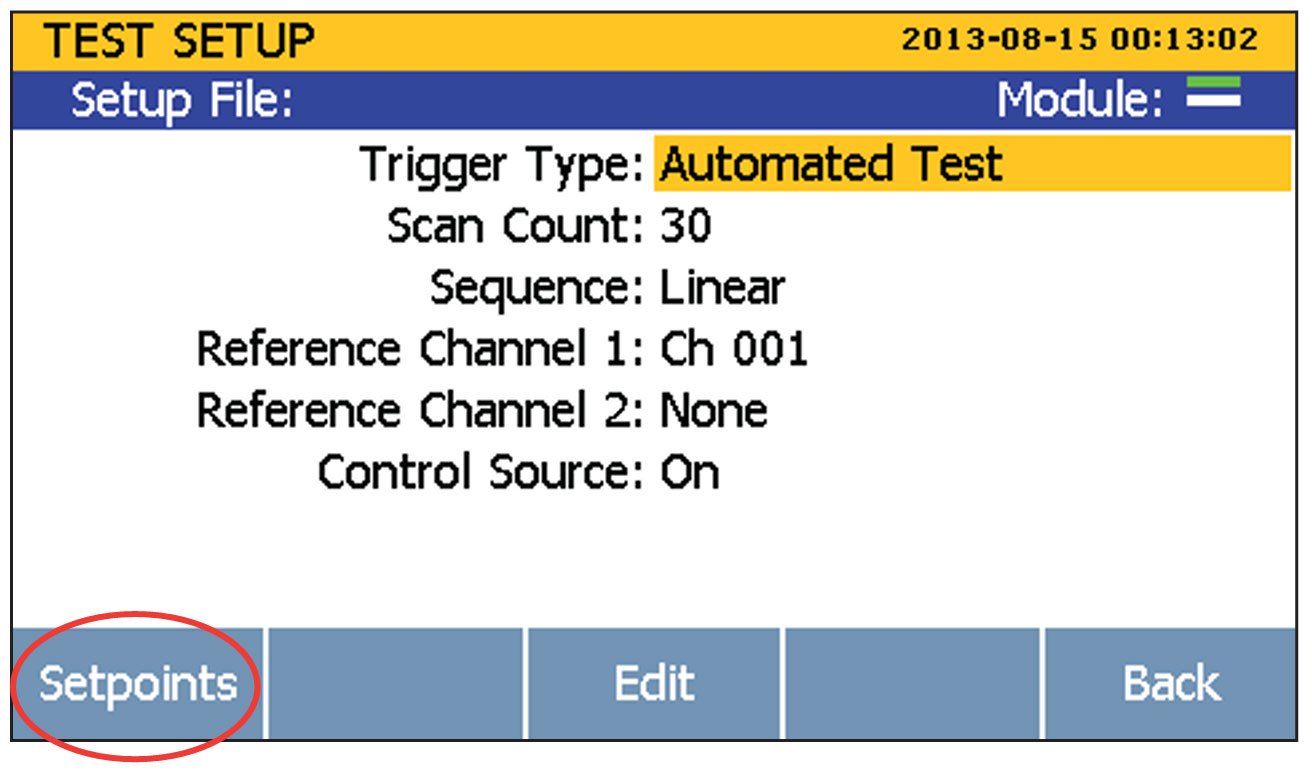
Press Test Setup. Change the Trigger Type to Automated Test, enter the Scan Count, set the Sequence to Linear, Alternate Reference, or Up/Down.
- Linear Sequence – Scans the first reference channel (Ref1), then all of the enabled channels in ascending channel order, followed by the optional second reference channel (Ref2). For example: Ref1 > Ch102 > Ch103 > Ch104 > Ref2.
- Alternate Reference Sequence – Scans the first reference channel (Ref1), then a single channel, followed by the optional second reference channel (Ref2). The sequence then repeats for the other enabled channels. For example: Ref1> Ch102 > Ref2 > Ref1 > Ch103 > Ref2 > Ref1 > Ch104 > Ref2.
- Up/Down Sequence – Scans the first reference channel (Ref1), then the enabled channels in ascending channel order, followed by the optional second reference channel (Ref2). The sequence is then immediately repeated in reverse, descending order. For example: Ref1 > Ch102 > Ch103 > Ch104 > Ref2 > Ref2 > Ch104 > Ch103 > Ch102 > Ref1.
Designate a Reference Channel and turn Control Source On. The default is Off, so don’t skip this step.
Note: If Auto Recording is On (Test Setup menu), data will be recorded automatically. If Auto Recording is Off, you can press the Record key once the scan has been started to manually capture data.
Step 4: Choose setpoint temperatures
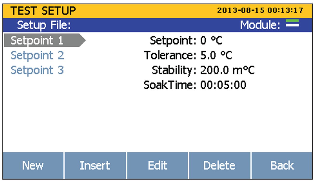
Press Setpoints. Select Setpoint 1 and enter Setpoint Temperature, Tolerance, Stability, and Soak Time. Press New to add additional setpoints.
Note: The number and value of setpoint temperatures is dependent on your source.
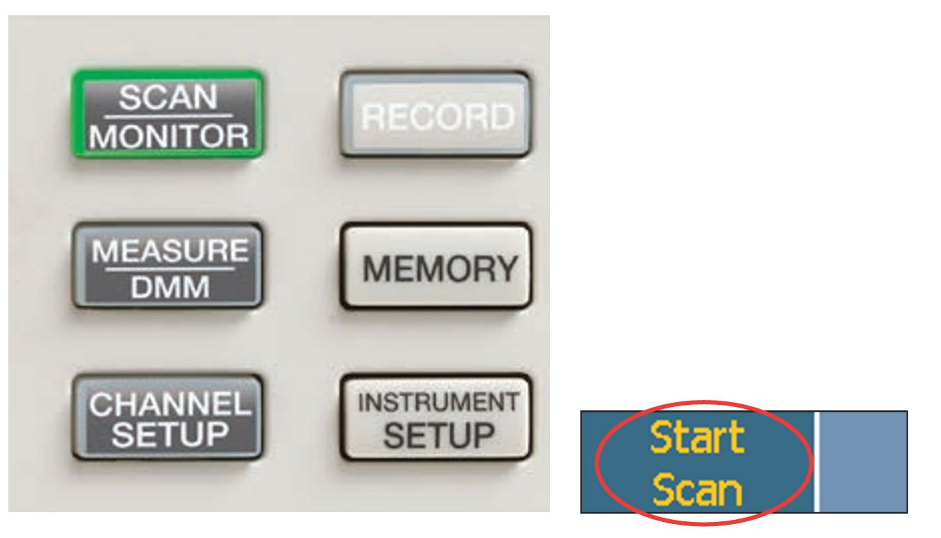
Step 5: Start the scan Press the Scan/Monitor key and select Start Scan.
Step 6: Collect data
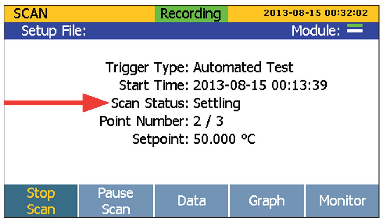
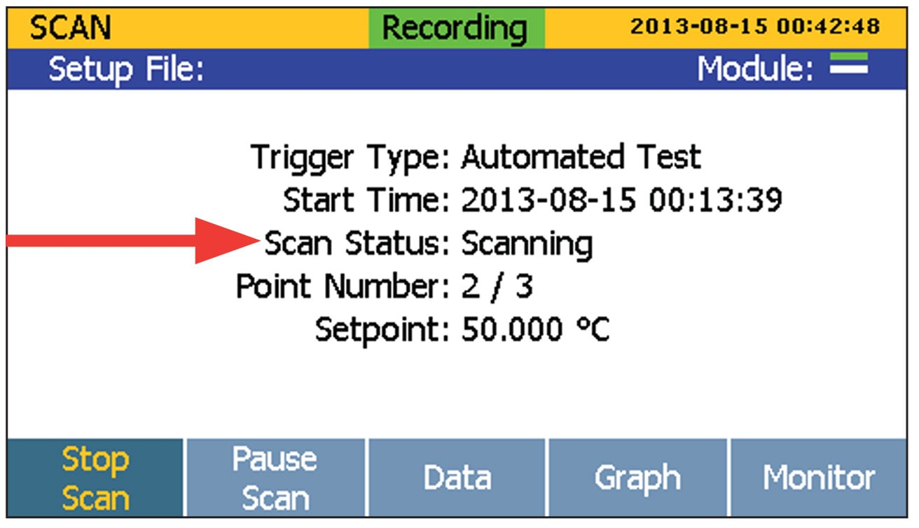
The Automated Test state will display a Scan Status of “Settling” while the temperature source is stabilizing. After the source has stabilized, the Automated Test state will then display a Scan Status of “Scanning” while the data is being collected. Data can be written to internal memory or a USB flash drive during a test. You can select Data, Graph, or Monitor view modes during data collection.
Step 7: Analyze data
Once the data has been collected, it can be transferred to a PC as an Excel .CSV file for analysis.
The automated sensor calibration feature of the 1586A Super-DAQ can have a big impact on your calibration lab throughput and efficiency. It comes in real handy when you have lots of sensors to calibrate and limited time and staff to do it. No extra training on software packages is needed.
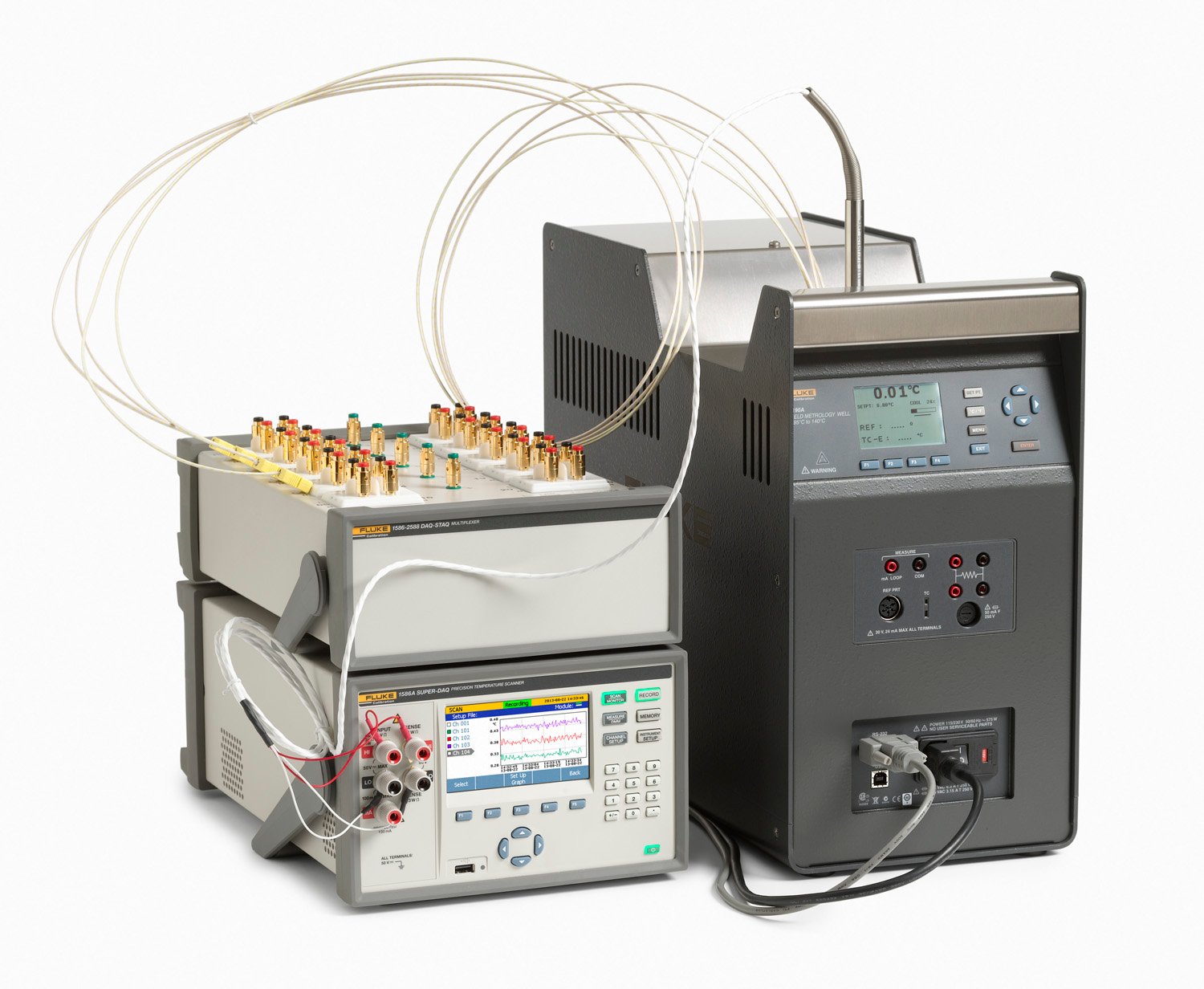
Once you set up a Super-DAQ automated test, you can move on to other work that needs to get done. The Super-DAQ controls the temperature source and gathers calibration data automatically—all within the parameters you’ve specified.