Measuring AC voltage is a crucial skill for electricians, engineers, and technicians working with electrical systems. Whether troubleshooting a circuit, ensuring power supply consistency, or verifying safety standards, an accurate voltage reading is essential.
Digital multimeters (DMMs) provide an effective and reliable means to measure AC voltage safely and precisely. This guide will outline the necessary steps to use a DMM for AC voltage measurement, discuss common precautions, and highlight additional features that can enhance accuracy and efficiency.
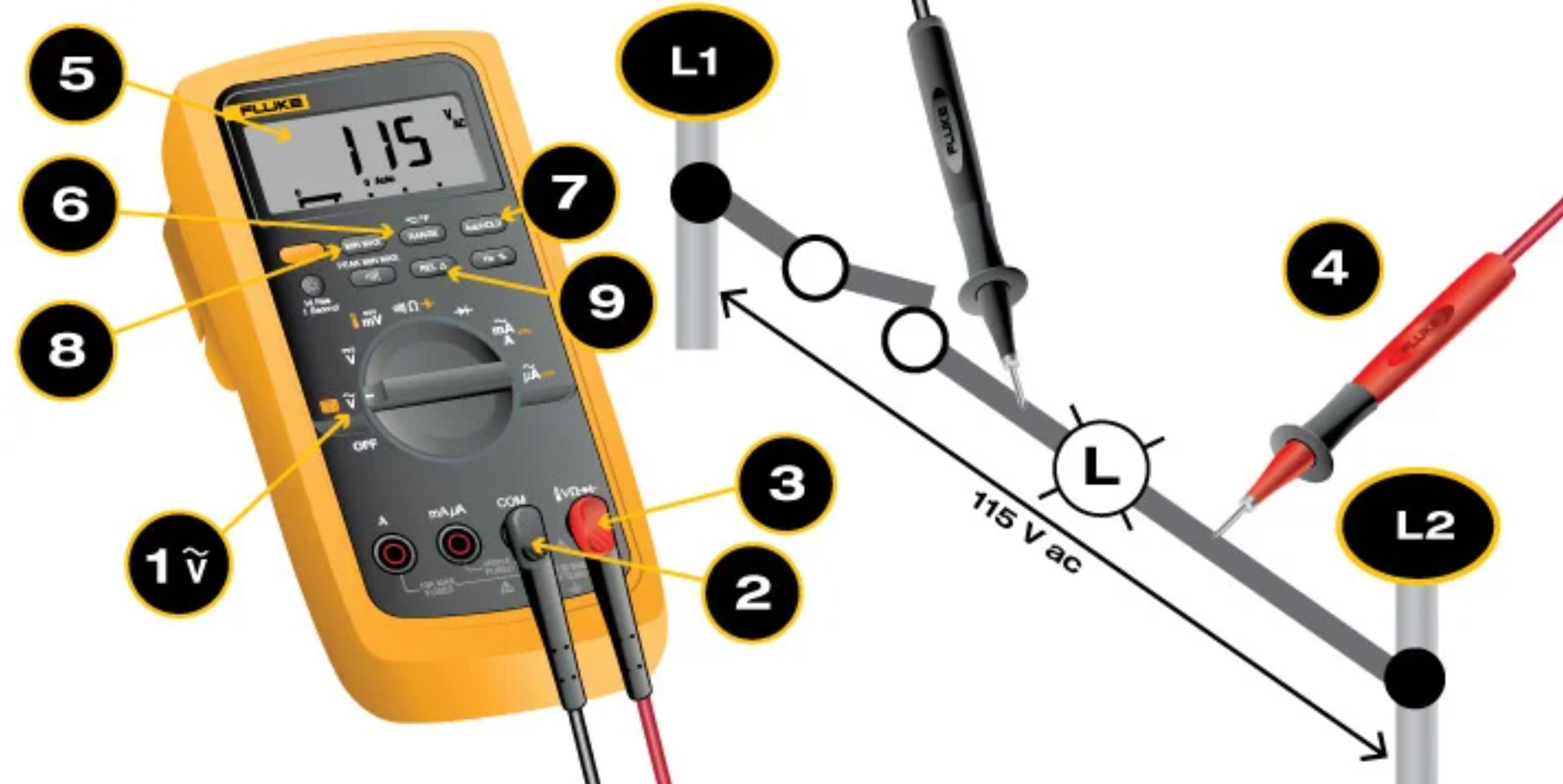
Step-by-Step Guide to Measuring AC Voltage
Step 1. Set the Digital Multimeter Dial to the Voltage Symbol
- Turn the dial to ṽ.
- Some digital multimeters (DMMs) also include m ṽ.
- If voltage in the circuit is unknown, set the range to the highest voltage setting and set the dial on ṽ.
- Note: Most multimeters power up in Autorange mode. This automatically selects a measurement range based on voltage present.
Step 2. Insert the black lead into the COM jack.
Step 3. Insert the red lead into the VΩ jack.
- When finished, remove the leads in reverse order: red first, then black.
Step 4. Connect the test leads to the circuit
- Connect the black lead first, red second.
- Note: AC voltage does not have polarity.
- Caution: Do not let fingers touch the lead tips. Do not allow the tips to contact one another.
Step 5. Read the measurement in the display.
- When finished, remove the red lead first, black second.
Advanced Multimeter Functions When Testing AC Voltage
Step 6. Select a Measurement Range
- Press the RANGE button to select a specific fixed measurement range.
Step 7. Capture a Measurement
- Press the HOLD button to capture a stable measurement. It can be viewed after the measurement is complete.
Step 8. Capture the Low and High Measurements
- Press the MIN/MAX button to capture the lowest and highest measurement. The DMM beeps each time a new reading is recorded.
Step 9. Set the Multimeter Reference Value
- Press the relative (REL) button to set the multimeter to a specific reference value. Measurements above and below the reference value are displayed.
Note: Avoid this common and serious mistake: inserting test leads into incorrect input jacks. Doing so can lead to a dangerous arc flash. If measuring ac voltage, be certain to insert the red lead into the input jack marked V, not A. The display should show the ṽ symbol. Placing test leads in A or MA inputs and then measuring voltage will create a short in the measurement circuit.
How to Analyze AC Voltage Measurements
- In general, all ac voltage sources vary from fluctuation in ac voltage over power distribution systems.
- When different from an expected measurement, voltage is more likely to be lower than normal.
- Generally speaking, voltage measured in ac power systems should be within -10% and +5%.
- Voltage measurements taken at various points in a system vary. Refer to the chart below.
| System Voltage Ranges* | ||||
|---|---|---|---|---|
| Supply | Service Range | Point of Use Range | ||
| Satisfactory | Acceptable | Satisfactory | Acceptable | |
| 120, 1Φ | 114 - 126 | 110 - 127 | 110 - 126 | 106 - 128 |
| 120/240, 1Φ | 114/228 - 126/252 | 110/220 - 127/254 | 110/220 - 126/252 | 106/212 - 127/254 |
| 120/208, 3Φ | 114/197 - 126/ | 110/191 - 127/220 | 110/191 - 126/218 | 106/184 - 127/220 |
| 120/240, 3Φ | 114/228 - 126/252 | 110/220 - 127/254 | 110/220 - 126/252 | 106/212 - 127/254 |
| 277/480, 3Φ | 263/456 - 291/504 | 254/440 - 293/508 | 254/440 - 291/504 | 264/424 - 293/508 |
* in volts
About Measuring AC Voltage
Accurately measuring AC voltage with a digital multimeter is essential for diagnosing electrical issues and ensuring systems operate within expected voltage ranges.
By following proper procedures—such as selecting the correct settings, using the right input jacks, and avoiding potential hazards—users can obtain reliable readings. Additional multimeter functions like HOLD, MIN/MAX, and REL provide further insights into voltage fluctuations. Understanding these principles helps maintain the integrity of electrical systems and promotes safety in various applications.