Large three-phase motors and the equipment they drive should consume power equally from each of the three mains phases. However, that often doesn’t happen. Unbalance and harmonics can cause instability, with motor vibration that reduces both efficiency and lifetime. Unbalance can also cause malfunctions in single-phase loads. All this can reduce your power quality, leading to punitive penalty charges from your utility.
In this blog, we will describe balanced three-phase power systems – where each of the phases draws the same current. In the next blog articles, published later, we will introduce unbalanced power.
Our previous blog showed how the infinitely variable instantaneous current and power waveforms can be simply represented by single numbers: parameters. Perhaps the most useful are active, reactive and apparent powers.
The active power does useful work, flowing through the resistive part of a network and having the same average value as the instantaneous power. The reactive power flows through the inductive part of the circuit 90° later and has an average value of zero. The apparent power is the total seen by the utility. The power factor is the active over the apparent power.
Balanced inductive/resistive loads
Three-phase resistive loads are straightforward, so we will go straight to inductive loads (which also incorporate a resistive component).
In a balanced system, the total active/reactive/apparent powers are simply the sum of their respective phase powers.
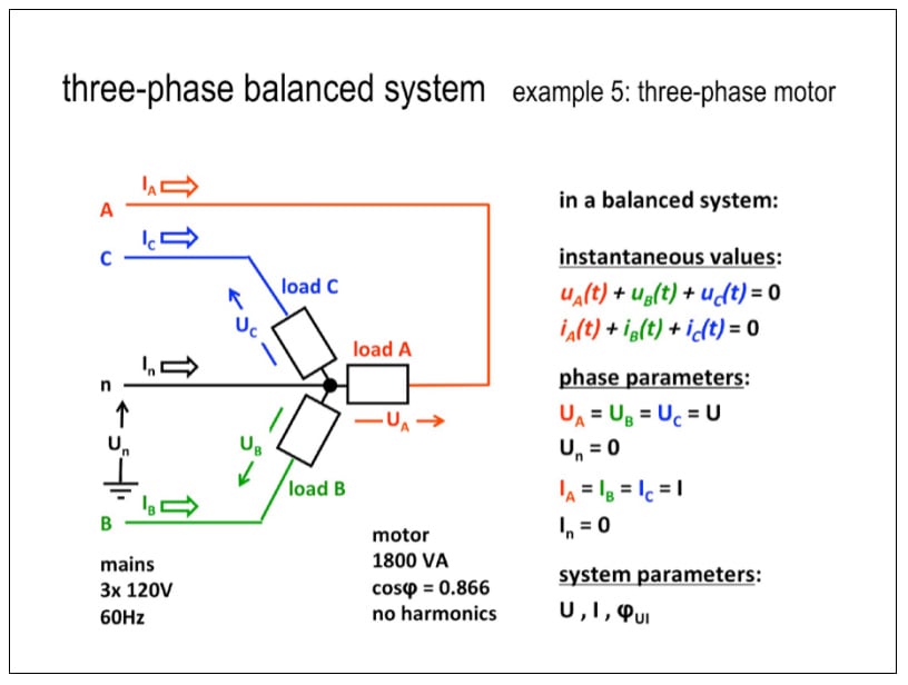
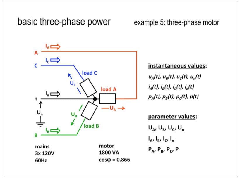 A basic three-phase power system with three 600 VA inductive loads. (The red, green and blue phase colors are just for demonstration and don’t follow any standard)
The sum of each of the voltages (and currents) at the star point is always zero. In a balanced system, the neutral current and neutral power is zero. You can think of a balanced three-phase system as three single-phase systems connected to a neutral line.
Voltage and current waveforms in a balanced system
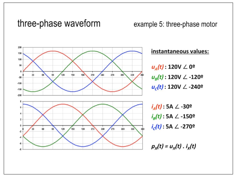 Three-phase voltage and current waveforms
Each voltage lags the previous one by 120° (look at the zero crossings). The motor also again introduces its own 30° phase shift between voltage and current.
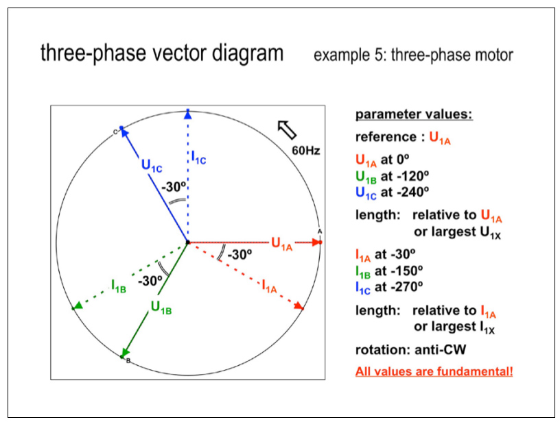 A vector (phasor) diagram shows the same information as the waveforms
This vector diagram shows just the fundamental values. The lengths of the lines represent the RMS values, and their heights above the origin show the instantaneous values. The whole thing turns at 60 times/sec counter-clockwise. Once again, the B and C phase voltages lag by 120° and 240°, and the A, B and C phase currents lag by 30°, 150° and 270°.
You could also draw a vector diagram for each harmonic component (but only the fundamental component normally transports useful energy).
Y and delta systems
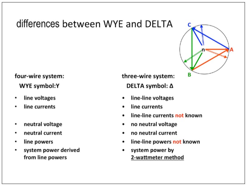 Differences between Y and Δ systems
There are differences between 4-wire WYE (Y) and 3-wire delta (Δ) systems. Unbalance is most easily demonstrated in Y systems so we will from now on again mainly consider them. The procedures for calculating unbalance are basically the same for Y and Δ, but the differences lie in the equations used.