By Chuck Newcombe

In a recent column I mentioned that Fluke was querying readers about their experiences with earth ground testing, so I thought we could revisit the subject in a little more detail this month.
What is the definition of grounding? What is the definition of bonding?
Articles 100 and 250 of the 2008 National Electrical Code (NEC) had many references to "bonding and grounding conductors." Unfortunately, this imprecise wording led to some confusion. The problem has been clarified somewhat in the 2011 code. References are now made to "bonding and grounding electrode conductors."
When you install a piece of service equipment in a facility, do you ground its metallic case to a ground rod? No. You bond it to a bonding conductor, sometimes referred to as an equipment grounding conductor. The purpose is to carry fault current back to the source, where that conductor is connected to the neutral so the current will cause a circuit breaker to trip. This is for personnel safety in the event that an electrical fault in a piece of equipment makes the metallic case "hot."
What is the purpose of the earth ground at a facility service entrance?
Will your driven ground rod, your "grounding electrode" as defined in the 2011 code, be effective for its intended purpose, which is to shunt high voltage surges from lightning and other sources from the service conductors to Earth?
When you drive an eight-foot ground rod into the ground near an electrical service entrance and hook it up, how do you know if it will be effective for its intended purpose?
A common practice has been to ensure that the grounding electrode resistance is less than 25 ohms, and if it isn't, to add additional electrodes in parallel at least six feet apart (more about this later), until that condition is met.
25 Ohms with respect to what?
When the ground rod to be tested has not yet been connected to the electrical system, or has been temporarily disconnected, the Fall of Potential test can be performed.
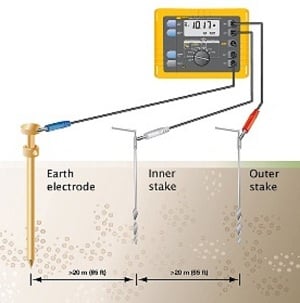
In a typical test for an 8-foot-long, 5/8-inch copper ground rod, the measuring circuit looks like Figure 1.

When wired as shown, one of the Fluke 162x series Earth Ground Testers forces a known current between the outer stake and the Earth electrode, creating a voltage gradient in the soil. The tester then measures the voltage drop between the inner stake and the earth electrode. Ohm's law calculations yield the resistance between the electrode and the inner stake.
Stakeless ground testing
In an active system, where the grounding electrode is already connected to the service neutral, there is a safer alternative to the Fall of Potential test. It doesn't require that the grounding electrode be disconnected from the system.

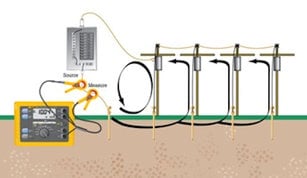
This method uses two current clamps (see Figure 2). The first current clamp is used as the primary of a transformer where the grounding electrode conductor is the secondary. Using this transformer, the tester applies a voltage source into the loop formed by the grounded utility system outside the facility and the service entrance. The second clamp senses the current flow in the loop, and then Ohm's law is again applied, calculating the resistance of the loop, which is primarily that of the earth between the facility grounding electrode and the utility grounding system.
I mentioned that parallel ground rods might be required in some installations. A common practice seemed to get around the testing requirement. Rather than testing the quality of a single ground, it is assumed that a second ground rod driven nearby (at least 6 feet away), parallel with the first one, is an adequate alternative. The fact is, with widely varying soil conditions, there is no guarantee that the "under 25 Ohms" requirement has been met. There is really no substitute for testing. Furthermore, even if the grounding system is tested at installation, there is no guarantee that it will remain viable over time. Corrosion and changing soil conditions can render the system ineffective. The only solution is to test it periodically.
Family of earth ground testers
The good news is that Fluke has a family of earth ground testers ranging from the handheld model 1630, which uses the stakeless method, to the model 1625 that can perform these tests using four different methods, including stakeless and the Fall of Potential method discussed above.
The stakeless method is the quickest and most convenient, since it doesn't require disconnecting and reconnecting the grounding electrode from the system. It is not suitable for new installations where utility service has yet to be connected. In this instance, the Fall of Potential test using three connections is appropriate.
I'm still eagerly awaiting the results of Fluke's recent queries to customers on the subject. Perhaps they will soon have some new features available that will make ground resistance testing even easier.