What is ground resistance testing? It is a test done to measure the resistance between a grounding electrode and earth. Specialized earth testers, like the Fluke 1630-2 FC Earth Ground Clamp and the Fluke 1625-2 GEO Earth Ground Tester, are the troubleshooting tools built to make earth ground tests a lot easier. How do you perform ground testing? Depending on the situation you’re in and what kind of ground setup you’re looking at, there are four different methods of testing earth ground resistance available.
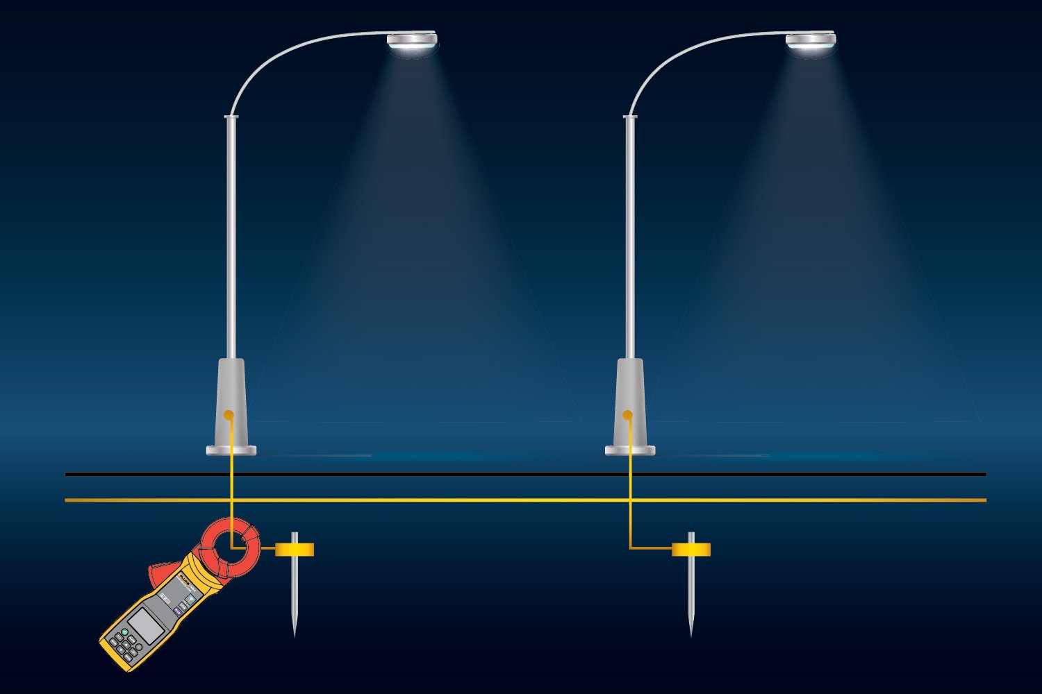
1. Stakeless earth ground testing
Stakeless testing uses only two clamps, one as a signal generator and one as a receiver, or one clamp like the 1630-2 FC, to make the measurements . It entirely eliminates the need for temporary ground stakes and is very useful when stakes can’t be driven into the ground. It also eliminates the dangerous and time-consuming process of disconnecting parallel grounds and finding a safe place to drive the stakes.
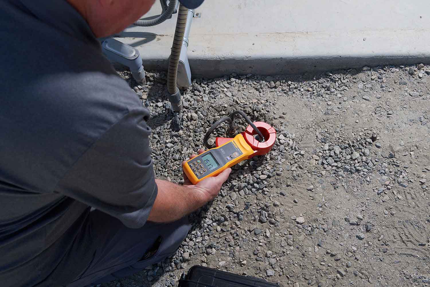
The stakeless method is the preferred method when parallel grounds are present and temporary ground stakes would be difficult to be driven in the ground. The stakeless method can be done with just one tool: the 1630-2 Earth Ground Clamp. Just clamp in on and measure away. You can use it both as a voltage generator and an amp clamp in one jaw. Plus, you can measure for low leakage current in a building at the same time.
You can also use this method with two clamps attached to a 1625-2. The first clamp is placed around the ground conductor and generates a voltage. The second clamp measures the current flowing due to the voltage generated from the first clamp.
2. Selective earth ground testing
The selective testing method uses one clamp and two stakes. It allows you to measure the ground resistance at specific parts of an installation, isolating the system to check or reference what’s in place.
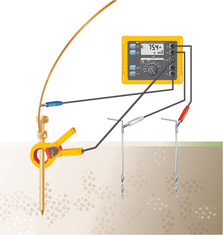
The selective testing method uses a current clamp while the electrode of interest is still under test. The clamp meter, like a Fluke 1625-2, is used to isolate the test current injected into the electrode under test.
Two earth stakes are placed in the soil in a direct line away from the electrode of interest, usually spacing of 20 meters is sufficient. The clamp meter is connected to the electrode and the Earth Ground Clamp meter is placed around the electrode to eliminate the effects of parallel resistances in a ground system. This allows only the earth electrode of interest to be measured.
3. Soil resistivity earth ground test
The soil resistivity measurement method uses four stakes and is typically used before installing an earthing arrangement. The soil composition, moisture content, and temperature all impact the resistance measurements you’ll see, so this testing is necessary to determine the design when installing a new grounding system. Taking these steps to check out the site before figuring out the layout or building begins. Ideally, you’d want to find a location with the lowest possible resistance to work with. This is also used to reassess an environment after, for example, a drought.
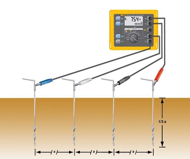
To test soil resistivity, connect the Fluke 1625-2 to four stakes in the ground. The earth ground tester will generate a known current through the outer two stakes and the inner two will measure any drop in voltage potential. The tester then automatically calculates soil resistance using Ohms law.
4. Fall of Potential earth ground test
Fall of potential measurement uses two stakes and the electrode under test to prove the correct installation of a system, check the grounding system that’s already in place before building, or this type of test can be used as part of a continued maintenance program.
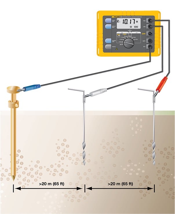
To run a test with this method, you first have to make sure the ground electrode of interest is disconnected from the site. Once that’s done you place two earth stakes in the soil in a direct line–line them up away from the earth electrode of interest, usually 20 meters apart is sufficient.
The 1625-2 will generate a known current between the outer stake and the ground electrode while the inner stake measures for any drop in voltage potential.
Ground testing requirements
Ideally, the ground resistance of a system is zero ohms, but in reality, this isn’t always achievable. Both the National Fire Protection Association (NFPA) and IEEE recommend a ground resistance value of 5.0 ohms or less. But, when you dive further into the National Electric Code (NEC), section 250.56 says that you want to make sure the system to ground is 25.0 ohms or less. In facilities with sensitive equipment, it should be 5.0 ohms or less. It all boils down to a goal of achieving the lowest ground resistance possible that makes sense economically and physically.
The NEC also requires a minimum electrode length of 2.5 meters (8 feet) to be in contact with the soil in order to have a ground resistance system. But there are also four variables that affect ground resistance in a ground system:
- Length / Depth of the ground electrode: double the length, reduce ground resistance by up to 40%
- Diameter of the ground electrode: double the diameter, lower ground resistance by only 10%
- Number of ground electrodes: for increased effectiveness, space additional electrodes at least equal to the depth of the ground electrodes
- Ground system design: single ground rod to ground plate
Each electrode must also be the proper spacing between them to reduce or eliminate their spheres of influence. This will vary depending on the size and shape of the conducting material. The proper distance apart ensures the test stakes are not influenced by one another, or a ground system under test.