During the eight years I've been writing this column, I've discussed wiring and grounding problems in industrial plants, homes, and dairy farms. This month, I'm going to add boat docks.
If you thought electrical leakage currents were dangerous in a kitchen or bathroom, consider what can happen when an unsuspecting swimmer comes near a boat with stray ac leakage current flowing between the boat hull and grounded dock components or the bottom of a lake. (See the report Electric Shock Drowning Incidents-Marinas©.)
The grim reality is that an ac leakage current, often less than 100 milliamps, may be flowing undetected in the water. That's far from the amount required to trip a 20-amp breaker, but enough to paralyze a swimmer. You wouldn't see any thrashing in the water, or hear a call for help. Later, a drowned person would be pulled from the water with no clue provided as to the cause of the drowning.
Unfortunately, I'm aware of such a case that occurred at a private dock on a lake. In that case, the person who discovered the swimmer felt a slight shock as he put his hand into the water and wisely turned off the power at the breaker box before attempting a rescue (which was, unfortunately, unsuccessful).
Ac power is present on a dock for lighting, winch operation, or at receptacles where an extension cord may be connected to carry power to tools used on the dock, or onboard a boat to run a battery charger connected to the boat's dc power system. Any one of those devices, on the dock or on the boat, can provide a path for electrical current to flow to ground through the water due to miswiring or a fault condition.
How can you detect the likely presence of small ac leakage currents in the water?
Among the many tools offered by Fluke for testing ac circuits is the model 360 AC Leakage Clamp Meter. This meter can measure up to 60 amps ac in normal use, but has two special features that make it appropriate for leakage current testing.
- The current measurement sensitivity extends down to a 3 mA range with 1 µA resolution.
- The jaw size is 1.5 inches (3.81 centimeters), allowing the jaws to be placed around thick cables and conduit.
Where to measure
In 1845, Gustav Kirchoff expressed a rule about current flowing through a node in an electrical circuit. It states that the sum of all currents flowing into and out of a node must equal zero. We can use this information to devise a test procedure for a dock, with or without a boat present. In the diagram below, the node we'll use is marked "N." Arrows with solid lines show where current should flow, and the dotted lines show where leakage can occur.

If you want to measure the current flowing from the source to the load, you would place the clamp around a single conductor (#1).
But, using Kirchoff's current law you can place the clamp around multiple conductors as shown at positions #2 and #3.
In a properly wired circuit, the clamp meter reading should be zero for positions #2 and #3. Any leakage current flowing in the green safety ground wire would be seen as a non-zero reading at position #2, and any leakage current from the load to earth would show a non-zero reading at positions #2 or #3. Since the green wire is included in the test at position #3, only the ground current is registered as leakage in that case.
I've shown a 120v single phase circuit here, but Kirchoff's current law works just as well for 240/120 volt circuits or three phase circuit cables with up to 5 conductors. If there is no stray leakage to ground from the load, a leakage clamp meter placed around the cable should read zero.
How much leakage current is ok?
Ideally, there should be no stray current flowing from the circuit, but leakage capacitances and some noise filter devices can cause small amounts of current to flow even in a properly operating system.
A Ground Fault Circuit Interrupter (GFCI) device, either as a breaker, a receptacle, or an in-line device can ensure that no lethal current will flow to ground from a protected load. GFCI devices use Kirchoff's principle to sense the current in the line and neutral conductors (position #2 in the diagram) and open the circuit if the net current exceeds 6 mA.


Demonstrating Kirchoff's current law in action
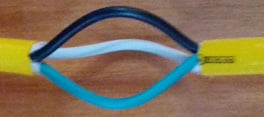
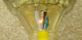
I've made an accessory to allow convenient measurements in the three test positions shown in the diagram above. I bought a short extension cord with a triple outlet and modified it as shown here to make the three conductors individually accessible.
When I plugged the cord into an outlet with nothing connected to the receptacle end, I measured the current around the single black conductor (test #1) and registered 1.480 mA. That's because the three-receptacle head on my cord has a neon pilot light in it telling me that the cord is live. Measurements in the #2 (white and black) and #3 (white, black, and green) positions read from 0.000 to 0.002 mA, confirming that all of the current powering the light was flowing in only the line and neutral - just as it should be.

Using my test adapter, a circuit wiring tester such as the Fluke T+PRO, and the Fluke model 360, you can quickly troubleshoot wiring problems involving leakage currents, and test GFCI devices for proper operation.
It's a small price to pay to keep docks, marinas, swimming pools, and our own backyards safe while using electrical devices, don't you think?