It takes basic research and a lot of hard work to make primary standards that meet today’s demanding requirements. But how do scientists research the behavior of a sealed system like a triple point of argon cell? You can’t see what’s going on inside, and you can’t know what you can’t see. Or can you?
Realizing the ITS-90
The triple point of argon (83.8058 K ) is one of the most commonly used fixed points for the calibration of standard platinum resistance thermometers (SPRTs) at temperatures below 273.16 K. It’s a defining fixed point of the International Temperature Scale of 1990 (ITS-90). Fluke Calibration recently designed a new Triple Point of Argon System with the goal in mind of achieving both efficiency and accuracy in calibrating SPRTs.
The design of a triple point of argon system is very complex, and many factors can influence the performance of the instrument. At the same time, the desired uncertainties of a triple point of argon system are very low which means the design needs to address many influences that could potentially affect the fixed point temperature, its stability, and the useful duration of the plateau.
Computer simulation
To meet this challenge a designer would like to know exactly what is happening inside. However, as a sealed system it is impossible to see inside the instrument, and make kinds of measurements a scientist would like to make. To overcome this challenge a team from Fluke Calibration used a modeling technique known as Finite Element Analysis (FEA) to “see” inside the sealed system for basic research and to make improvements on the design.
The physics that governs the heat flows in the triple point of argon system is described by a system of partial differential equations. These thermodynamic equations can be notoriously difficult to solve especially in a complex system like the triple point of argon cell.
Finite Element Analysis is a numerical technique for solving these equations and modeling what is really happening behind the scenes. By the way, FEA has been also been used to solve complex mechanical deformation and heat transfer problems in other industries such as automobile and aerospace.
Imagine a computer model of the triple point of argon system made up of a mesh of crisscrossing lines. The regions between the lines are called elements. There are nearly 712,000 elements in the model used to analyze the thermodynamics of the triple point of argon cell. In the course of the analysis, billions of calculations are performed by a computer before a solution is reached.

Figure 1. Model of a triple point of argon cell reentrant well

Figure 2. Simulation of temperatures in a triple point of argon cell reentrant well
The Fluke Calibration Design
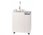
The Fluke Calibration triple point of argon system was modeled after a NIST design. It includes a high-accuracy temperature controller with resolution of 1.0 mK for the temperature set point, two argon gas reservoir cylinders, and a central argon cell with four stainless steel re-entrant wells for calibrating up to four SPRTs at one time.
Figure 3. Fluke Calibration triple point of argon system schematic
Read the paper
In this paper by R.Ding, M.J. Zhao, T. Nielson, E. Nerdrum, and D. Farley called “Experimental Study and Computer Modeling of the Triple Point of Argon System” key results are shared from their modeling and physical experiments of a triple point of argon system:
Key results
- A plateau can last 100 hours with temperature changes less than 0.05 mK
- The uncertainty analysis shows a total combined uncertainty of 0.26 mK
- The ideal maintenance temperature is 20 mK above the triple point of argon
Read the paper if you’d like to see more of the images generated by the simulation and compare the results to actual measurement data.
- See the FEA mesh used to simulate the central assemble of the argon system
- See images of the simulated temperatures of the heater shield and central argon cell.
- See images of the simulated temperatures of the four re-entrant wells
- See how the data showing how the tested immersion profile of the re-entrant wells closely follows the ITS-90 theoretical values