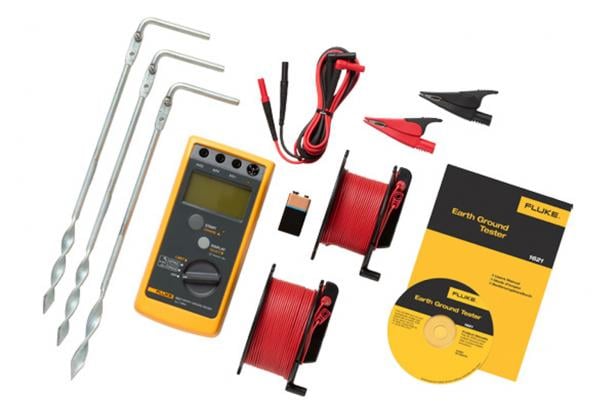
Fluke 1621 Kit - Basic Earth Ground Tester
Discontinued
Key Features
- 3-pole Fall-of-Potential earth testing for basic measurements
- 2-pole resistance measurements for added versatility
- Easily capture values with single-button operation
- Ensure accurate measurements with automatic ‘noise’ voltage detection
- Hazardous voltage warning offers increased user protection
- Clearly read and record data with a large, backlit display
- Hard carrying case
- Rugged holster and design for tough work environments
- Portable size allows for easy transportation
- Instantly be alerted to measurements outside of your set limit, when you use the adjustable limit setting
- 600 V Cat II
This product is discontinued or reclassified
Fluke suggests:Fluke 1623-2 GEO Earth Ground Tester Kit
Product overview: Fluke 1621 Kit - Basic Earth Ground Tester
The Fluke 1621 Kit is an easy-to-use earth ground tester. For ground resistance testing, the 1621 Kit is the first line of defense in detecting reliable ground connections. The unit features basic ground testing methods including 3-pole Fall-of-Potential as well as 2-pole ground resistance tests. Its convenient size, rugged holster, and large, clear LCD display make it an ideal field earth ground tester, for most electrical grounding work environments. With a simple user interface and intuitive functionality, the Fluke 1621 Kit is a handy grounding tool for electrical contractors, utility test engineers, and earth ground specialists.
Specifications: Fluke 1621 Kit - Basic Earth Ground Tester
| General Specifications | ||
| Measuring functions | 3-pole earth ground resistance, 2-pole AC resistance of a conductor, Interference voltage | |
| Intrinsic error | Refers to the reference temperature range and is guaranteed for one year | |
| Measuring rate | 2 measurements/second | |
| Battery1 | One 9 volt alkaline (LR61) | |
| Battery condition | LO-BAT is displayed if voltage drops below 6.5 V | |
| Voltages | Between jacks H/C2 and E/C1 | 250 Veff maximum (effective voltage) |
| Between jacks S/P2 and E/C1 | 250 Veff maximum | |
| Climatic class | VDE/VDI 3540 RZ (conforming to KWG as per DIN 40040, 4/87) | |
| Temperature performance2 | Working | -10°C to +50°C (+14°F to +122°F) |
| Operating | 0°C to +35°C (+32°F to +95°F) | |
| Storage | -20°C to +60°C (+68°F to +140°F) | |
| Reference | +23°C ±2°C (+73°F ±4°F) | |
| Temperature coefficient | ±0.1% of range per degree Kelvin | |
| Safety | IEC/EN 61010-1, 600 V CAT II, pollution degree 2 | |
| Dimensions | 113 x 54 x 216 mm (4.5 x 2.1 x 8.5 in), including holster | |
| Weight | 850 g (1.9 lb), including standard accessories, volume approximately 600 cm3 | |
| Electrical Specifications | ||
| Maximum deviations | E1 Influence factor | Position |
| E1 Deviation influence | 0% | |
| E2 Influence factor | Supply voltage | |
| E2 Deviation influence | 0% | |
| E3 Influence factor | Temperature E3 | |
| E3 Deviation influence | 2.3% | |
| E4 Influence factor | Serial interference voltage (20 V) | |
| E4 Deviation influence | 0.6% | |
| E5 Influence factor | Probe- and auxiliary probe resistance | |
| E5 Deviation influence | 10% | |
| Test voltage | 3.7 kV | |
| Protection type | IP 40; IEC/EN 60529 | |
| Electromagnetic compatibility | Emission | IEC/EN 61326 Class B |
| Immunity | IEC/EN 61326 Annex C | |
| RE resistance measurement | Measuring method | Current-voltage measurement with improved cross-talk attenuation, no compensation of measuring lead resistance, with probe (3-pole) or without probe (2-pole), as per IEC/EN 61557-5 |
| Open circuit voltage | 23 to 24 V AC | |
| Short circuit current | > 50 mA AC | |
| Measuring frequency | 128 Hz | |
| Maximum permissible overload | 250 Veff | |
| Measuring time | 8 seconds (average from when START is pressed) | |
| Limit input | Tester retains set value even if instrument is turned off (assuming battery power supply is sufficient) | |
| Automatic changeover of resolution | RH | < 7 kΩ |
| Resolution | 0.01 Ω | |
| RH | < 50 kΩ | |
| Resolution | 0.1 Ω | |
| RH | > 50 kΩ | |
| Resolution | 1 Ω | |
| Interference voltage display DC + AC | Vmax | 30 Veff |
| Common mode rejection | > 80 dB at 50 Hz and 60 Hz | |
| Ri | 680 kΩ | |
| Measuring uncertainty | < 10% for pure AC and DC signals | |
| Measuring Range | ||
| 0.15 Ω to 20 Ω | Resolution | 0.01 Ω |
| Display range | 0 to 19.99 Ω | |
| 200 Ω | Resolution | 0.1 Ω |
| Display range | 20 to 199.9 Ω | |
| 2 kΩ | Resolution | 1 Ω |
| Display range | 200 to 1999 Ω | |
| Intrinsic uncertainty | ±(6% of measured value + 5D) | |
| Operating uncertainty IEC 615573 | ±(18% of measured value + 5D) | |
| 1. If the tester is not going to be used, or is being stored for a long period, remove the battery and store separately from the tester to avoid damage from battery leakage. 2. The four temperature ranges for the tester exists to satisfy European Standards requirements; the instrument can be used over the full working temperature range by using the temperature coefficient to calculate accuracy at the ambient temperature of use. 3. Covers all deviations caused by influence quantities E1-E5. If the deviation E4 caused by high probe or auxiliary probe resistance is higher than specified flashes. Measured values are outside of the specified operating uncertainty. | ||


