You'll find motor drive and electric motors in settings including residential, commercial, industrial, entertainment, government, and anywhere else requiring controlled rotating output.
Problems can sometimes arise with control requirements or environmental conditions. Motor and drive applications can face problems such as blown fuses or tripped circuit breakers; equipment can be damaged as a result of moisture, dirt, oil or grease, corrosion, lightning, mishandling, and any conditions beyond what the equipment was designed to handle. Equipment damage might also result from age, overuse, improper sizing, misalignment, and power conditions including transient voltages, harmonics, loss of phase, and voltage sags and swells.
Electric motors are one of the most reliable pieces of electrical equipment around, provided that they are used and installed correctly, with the proper size and power source connection taken into account. In such conditions, they could be expected to last for a decade or more with minimal maintenance required.
Single-phasing can be difficult to detect
Still, motors can and do fail. A three-phase motor can lose one of the phase voltages, resulting in a problem called single-phasing, which can be difficult to detect under normal operating conditions. In a variable speed drive (VSD), single-phasing is typically caused by an open connection at one end of the cabling between the motor and drive, or in one of the cable conductors. Other causes of single-phasing include blown fuses, mechanical failure within the switching equipment, and even lightning strikes.
When single-phasing happens, the other two phase windings have to conduct more current, which produces excess heat and leads to motor failure. Single-phasing can be difficult to detect because in many cases the motor will continue to run. Thus, taking current measurements on all phases until an open phase has been detected is the best way to pinpoint single-phasing.
Flashover currents to outer bearings
A motor creates unavoidable shaft voltage from the stator winding to the rotor shaft because of small asymmetries in the magnetic field in the air gap. When motor shaft voltages exceed the insulating capacity of bearing grease, flashover currents to outer bearings can happen. Unusual loud noises and overheating are common first signs of the problem, caused by bearings that are beginning to lose their shape and see an increase in friction. Shaft voltages must be measured with a portable oscilloscope rather than a digital multimeter (DMM) because the voltages appear as inconsistent peaks. The variation between these peaks is not significant enough for a DMM to register it.
Common tools for troubleshooting

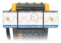
Portable oscilloscopes are the ideal tool in a number of situations because of their advanced features. On a portable oscilloscope display, the (x) axis represents time and the (y) axis represents the amplitude of a waveform. A trace is a line on the display that shows a signal's amplitude over time. It can be adjusted with the time base setting. Multichannel portable oscilloscopes can display up to four traces at once.
Mechanisms allow for adjustments to be made to both horizontal and vertical positioning, which allows for two different measured values to be overlaid. Displaying measurements in this way makes clear whether measurements are in-phase or out-of-phase with each other. The more out-of-phase the measurements are, the bigger is the existing difference between the circuit's true power and apparent power. A circuit with a difference between true power and apparent power is one that has a poor power factor.
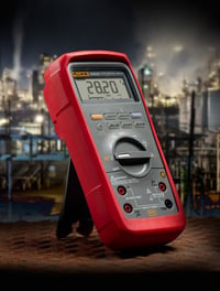
Digital multimeters, or DMMs, are another common test tool. They measure electrical properties and display the properties in numerical values. Typically, they are used for basic voltage, resistance, and current measurements of basic devices such as fuses and switches. They can also be used for basic troubleshooting measurements, such as voltage or current to motor. There are different categories of DMMS: general purpose, standard, and advanced.

General purpose DMMs are used for measuring voltage at the source. Additionally, they can be used to measure voltage between phases, such as phase-to-ground and phase-to-neutral. However, general purpose DMMs are not always as accurate as their more advanced counterparts, and they have more limitations.
A standard DMM has several features and capabilities beyond those of a general purpose DMM, such as the ability to test diodes and capacitors directly, and extra selector switch positions to use for taking low-impedance current and voltage measurements. Standard DMMs also can display bar graphs rather than numerical displays alone.
Advanced DMMs include additional features such as displays with capacities for more accurate measurements; the ability to capture and store measurements taken for later viewing; and trending features that allow measurements that have been taken over time to be displayed as a single line on a graph.
While general purpose DMMs are useful for most applications, when troubleshooting it makes sense to have available an advanced DMM with several attachments. Measurements taken on some advanced DMMs can be downloaded to a PC for later viewing, which allows for thorough monitoring of performance over time.