Understanding the role of a continuity tester in electrical diagnostics is crucial for professionals and enthusiasts alike. This guide offers a step-by-step approach on how to use a digital multimeter as a continuity tester, ensuring precise and safe measurements. Whether you're testing switches, fuses, or making general electrical connections, mastering the use of a continuity tester is key to effective electrical troubleshooting.
How to Setup Your Digital Multimeter to Test for Continuity
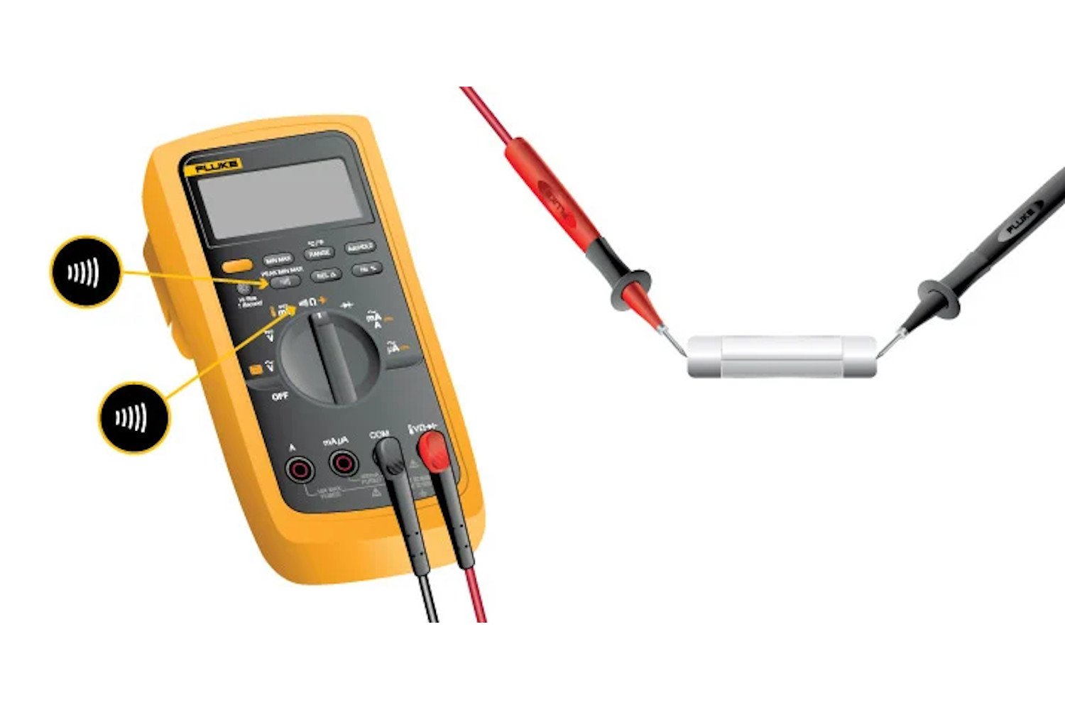
To begin, it's essential to properly set up your digital multimeter for the continuity test. This involves:
- Selecting the Correct Mode: Turn the dial to Continuity Test mode. It's common for this mode to be combined with other functions, typically resistance (Ω). With the test probes separated, the multimeter’s display may show OL and Ω.
- Activating Continuity Mode: Some models require you to press a continuity button to activate this specific testing mode. Ensure this step is followed if your multimeter has this feature.
Step-by-Step Guide to Test Continuity with a Digital Multimeter
Once your digital multimeter is set up, follow these steps to conduct the continuity test:
Step 1. Connect the Test Leads
- First, insert the black test lead into the COM jack.
- Then, insert the red lead into the VΩ jack.
- Always remove the leads in reverse order after testing: red first, then black.
Step 2. Test the Circuit
- With the circuit de-energized, connect the test leads across the component being tested.
- The position of the test leads is arbitrary, but ensure the component is isolated from other components in the circuit.
Step 3. Interpret the Results
The digital multimeter (DMM) emits a beep if a complete path (continuity) is detected. If the circuit is open (the switch is in the OFF position), the DMM will not beep.
Step 4. Conclude the Test
- When finished, always turn the multimeter OFF to conserve battery life.
Principles and Practices of Testing Continuity with a Digital Multimeter
Continuity is the presence of a complete path for current flow. A circuit is considered complete when its switch is closed. Here are some key points to remember:
- Applications of Continuity Testing: A digital multimeter’s Continuity Test mode is versatile, suitable for testing switches, fuses, electrical connections, conductors, and other components. For example, a good fuse should show continuity.
- Audible Indicator: The beep is an audible response from the DMM when it detects a complete path, allowing technicians to focus on the test without needing to constantly monitor the display.
- Understanding Resistance and Beeps: The beep is triggered based on the resistance of the component being tested, influenced by the multimeter's range setting. For instance, at a 400.0 Ω range setting, a multimeter typically beeps if the component has 40 Ω or less resistance.
- Optimal Range Setting: Use the lowest range setting for testing components that should have a low-resistance value, such as electrical connections or switch contacts.
Additional Resources for Digital Multimeter Applications
Build your skills with a digital multimeter by exploring these related resources:
- How to Test Diodes with a Digital Multimeter: Delve deeper into the use of a digital multimeter for testing diodes, an essential component in many electronic circuits.
- How to Measure Current with a Clamp Accessory: Learn the technique of measuring electrical current safely and accurately using a clamp accessory with your digital multimeter.